
Datasheet

STM32F100x4, STM32F100x6, STM32F100x8, STM32F100xB Revision history
Doc ID 16455 Rev 7 85/88
8 Revision history
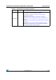
Table 54. Document revision history
Date Revision Changes
12-Oct-2009 1 Initial release.
26-Feb-2010 2
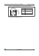
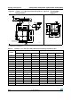
TFBGA64 package added (see Table 50 and Ta bl e 41 ).
Note 5 modified in Table 4: Low & medium-density STM32F100xx pin
definitions.
I
INJ(PIN)
modified in Table 6: Current characteristics. Conditions
removed from Table 25: Low-power mode wakeup timings.
Notes modified in Table 34: I/O static characteristics.
Figure 27: Recommended NRST pin protection modified.
Note modified in Table 39: I2C characteristics. Figure 28: I2C bus AC
waveforms and measurement circuit(1) modified.
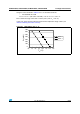
Table 46: DAC characteristics modified. Figure 36: 12-bit buffered
/non-buffered DAC added.
TIM2, TIM3, TIM4 and TIM15, TIM16 and TIM17 updated.
HDMI-CEC electrical characteristics added.
Values added to:
– Table 12: Maximum current consumption in Run mode, code with
data processing running from Flash
– Table 13: Maximum current consumption in Run mode, code with
data processing running from RAM
– Table 14: Maximum current consumption in Sleep mode, code
running from Flash or RAM
– Table 15: Typical and maximum current consumptions in Stop and
Standby modes
– Table 18: Peripheral current consumption
– Table 29: EMS characteristics
– Table 30: EMI characteristics
– Table 47: TS characteristics
Section 5.3.12: I/O current injection characteristics modified.
Added figures:
– Figure 12: Maximum current consumption in Run mode versus
frequency (at 3.6 V) - code with data processing running from RAM,
peripherals enabled
– Figure 13: Maximum current consumption in Run mode versus
frequency (at 3.6 V) - code with data processing running from RAM,
peripherals disabled
– Figure 15: Typical current consumption in Stop mode with regulator
in Run mode versus temperature at VDD = 3.3 V and 3.6 V
– Figure 16: Typical current consumption in Stop mode with regulator
in Low-power mode versus temperature at VDD = 3.3 V and 3.6 V
– Figure 17: Typical current consumption in Standby mode versus
temperature at VDD = 3.3 V and 3.6 V