
Datasheet


STM32F051x Electrical characteristics
Doc ID 022265 Rev 3 87/105
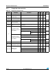
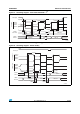
Figure 25. I
2
C bus AC waveforms and measurement circuit
1. Measurement points are done at CMOS levels: 0.3 V
DD
and 0.7 V
DD
.
SPI/I
2
S characteristics
Unless otherwise specified, the parameters given in Ta bl e 6 6 for SPI or in Ta bl e 6 7 for I
2
S
are derived from tests performed under ambient temperature, f
PCLKx
frequency and V
DD
supply voltage conditions summarized in Ta bl e 2 0 .
Refer to Section 6.3.13: I/O port characteristics for more details on the input/output alternate
function characteristics (NSS, SCK, MOSI, MISO for SPI and WS, CK, SD for I
2
S).
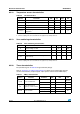
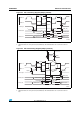
Table 65. I2C analog filter characteristics
(1)
1. Guaranteed by design, not tested in production.
Symbol Parameter Min Max Unit
t
SP
Pulse width of spikes that are
suppressed by the analog filter
50 260 ns
-36
34!24
3$ !
Ω
)
#BUS
2
Ω
6
$$
6
$$
-#5
3$!
3#,
T
F3$!
T
R3$!
3#,
T
H34!
T
W3#,(
T
W3#,,
T
SU3$!
T
R3#,
T
F3#,
T
H3$!
3 4!242%0%!4%$
34!24
T
SU34!
T
SU34/
34/0
T
W34/34!
2
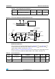
Table 66. SPI characteristics
Symbol Parameter Conditions Min Max Unit
f
SCK
1/t
c(SCK)
SPI clock frequency
Master mode - 18
MHz
Slave mode - 18
t
r(SCK)
t
f(SCK)
SPI clock rise and fall
time
Capacitive load: C = 15 pF - 6 ns