
Datasheet

STM32F051x Functional overview
Doc ID 022265 Rev 3 23/105
3.16 Inter-integrated circuit interfaces (I
2
C)
Up to two I
2
C interfaces (I2C1 and I2C2) can operate in multimaster or slave modes. Both
can support Standard mode (up to 100 kbit/s) or Fast mode (up to 400 kbit/s) and I2C1
supports also Fast Mode Plus (up to 1 Mbit/s) with 20 mA output drive.
Both support 7-bit and 10-bit addressing modes, multiple 7-bit slave addresses (2
addresses, 1 with configurable mask). They also include programmable analog and digital
noise filters.
In addition, I2C1 provides hardware support for SMBUS 2.0 and PMBUS 1.1: ARP
capability, Host notify protocol, hardware CRC (PEC) generation/verification, timeouts
verifications and ALERT protocol management. I2C1 also has a clock domain independent
from the CPU clock, allowing the I2C1 to wake up the MCU from Stop mode on address
match.
The I2C interfaces can be served by the DMA controller.
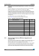
Refer to Ta ble 9 for the differences between I2C1 and I2C2.
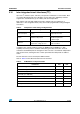
Table 8. Comparison of I2C analog and digital filters
Analog filter Digital filter
Pulse width of
suppressed spikes
≥ 50 ns
Programmable length from 1 to 15
I2C peripheral clocks
Benefits Available in Stop mode
1. Extra filtering capability vs.
standard requirements.
2. Stable length
Drawbacks
Variations depending on
temperature, voltage, process
Disabled when Wakeup from Stop
mode is enabled
Table 9. STM32F051x I
2
C implementation
I2C features
(1)
1. X = supported.
I2C1 I2C2
7-bit addressing mode
XX
10-bit addressing mode
XX
Standard mode (up to 100 kbit/s)
XX
Fast mode (up to 400 kbit/s)
XX
Fast Mode Plus with 20mA output drive I/Os (up to 1 Mbit/s)
X
Independent clock
X
SMBus
X
Wakeup from STOP
X