
Datasheet

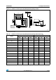
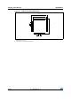

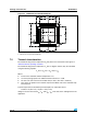


Package characteristics STM32F051x
102/105 Doc ID 022265 Rev 3
Note: With this given P
Dmax
we can find the T
Amax
allowed for a given device temperature range
(order code suffix 6 or 7).
Suffix 6: T
Amax
= T
Jmax
- (45°C/W × 447 mW) = 105-20.115 = 84.885 °C
Suffix 7: T
Amax
= T
Jmax
- (45°C/W × 447 mW) = 125-20.115 = 104.885 °C
Example 2: High-temperature application
Using the same rules, it is possible to address applications that run at high ambient
temperatures with a low dissipation, as long as junction temperature T
J
remains within the
specified range.
Assuming the following application conditions:
Maximum ambient temperature T
Amax
= 100 °C (measured according to JESD51-2),
I
DDmax
= 20 mA, V
DD
= 3.5 V, maximum 20 I/Os used at the same time in output at low
level with I
OL
= 8 mA, V
OL
= 0.4 V
P
INTmax
=
20 mA × 3.5 V= 70 mW
P
IOmax
=
20 × 8 mA × 0.4 V = 64 mW
This gives: P
INTmax
= 70 mW and P
IOmax
= 64 mW:
P
Dmax
=
70
+
64 = 134 mW
Thus: P
Dmax
= 134 mW
Using the values obtained in Table 7 2 T
Jmax
is calculated as follows:
– For LQFP64, 45 °C/W
T
Jmax
= 100 °C + (45 °C/W × 134 mW) = 100 °C + 6.03 °C = 106.03 °C
This is above the range of the suffix 6 version parts (–40 < T
J
< 105 °C).
In this case, parts must be ordered at least with the temperature range suffix 7 (see
Section 8: Part numbering) unless we reduce the power dissipation in order to be able to
use suffix 6 parts.
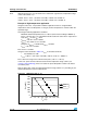
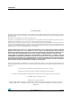
Refer to figure 38 to select the required temperature range (suffix 6 or 7) according to your
ambient temperature or power requirements.
Figure 39. LQFP64 P
D
max vs. T
A
0
100
200
300
400
500
600
700
65 75 85 95 105 115 125 135
T
A
(°C)
P
D
(mW)
Suffix 6
Suffix 7