
Datasheet


STM32F050xx Electrical characteristics
Doc ID 023683 Rev 1 45/97
upply current
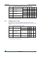
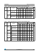
Table 22. Typical and maximum V
DD
consumption in Stop and Standby modes
Symbol Parameter Conditions
Typ @V
DD
(V
DD
= V
DDA
)Max
(1)
Unit
2.0 V 2.4 V 2.7 V 3.0 V 3.3 V 3.6 V
T
A
=
25 °C
T
A
=
85 °C
T
A
=
105 °C
I
DD
Supply
current in
Stop mode
Regulator in run mode,
all oscillators OFF
15 15.1 15.25 15.45 15.7 16 18
(2)
38 55
(2)
µA
Regulator in low-power
mode, all oscillators
OFF
3.15 3.25 3.35 3.45 3.7 4 5.5
(2)
22 41
(2)
Supply
current in
Standby
mode
LSI ON and IWDG ON 0.8 0.95 1.05 1.2 1.35 1.5 - - -
LSI OFF and IWDG
OFF
0.65 0.75 0.85 0.95 1.1 1.3 2
(2)
2.5 3
(2)
1. Data based on characterization results, not tested in production unless otherwise specified.
2. Data based on characterization results and tested in production.
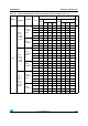
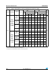
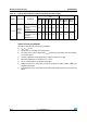
Table 23. Typical and maximum V
DDA
consumption in Stop and Standby modes
Symbol Parameter Conditions
Typ @V
DD
(V
DD
= V
DDA
)Max
(1)
Unit
2.0 V 2.4 V 2.7 V 3.0 V 3.3 V 3.6 V
T
A
=
25 °C
T
A
=
85 °C
T
A
=
105 °C
I
DDA
Supply
current in
Stop mode
V
DDA
monitoring ON
Regulator in run mode,
all oscillators OFF
1.85 2 2.15 2.3 2.45 2.6 3.5 3.5 4.5
µA
Regulator in low-power
mode, all oscillators
OFF
1.85 2 2.15 2.3 2.45 2.6 3.5 3.5 4.5
Supply
current in
Standby
mode
LSI ON and IWDG ON 2.25 2.5 2.65 2.85 3.05 3.3 - - -
LSI OFF and IWDG
OFF
1.75 1.9 2 2.15 2.3 2.5 3.5 3.5 4.5
Supply
current in
Stop mode
V
DDA
monitoring OFF
Regulator in run mode,
all oscillators OFF
1.11 1.15 1.18 1.22 1.27 1.35 - - -
Regulator in low-power
mode, all oscillators
OFF
1.11 1.15 1.18 1.22 1.27 1.35 - - -
Supply
current in
Standby
mode
LSI ON and IWDG ON 1.5 1.58 1.65 1.78 1.91 2.04 - - -
LSI OFF and IWDG
OFF
1 1.02 1.05 1.05 1.15 1.22 - - -
1. Data based on characterization results, not tested in production.