
Datasheet


Electrical characteristics STM32F050xx
40/97 Doc ID 023683 Rev 1
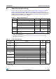
6.3.2 Operating conditions at power-up / power-down
The parameters given in Ta bl e 1 6 are derived from tests performed under the ambient
temperature condition summarized in Tabl e 1 5 .
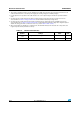
6.3.3 Embedded reset and power control block characteristics
The parameter given in Ta bl e 1 7 is derived from tests performed under ambient temperature
and V
DD
supply voltage conditions summarized in Table 15: General operating conditions.
Table 16. Operating conditions at power-up / power-down
Symbol Parameter Conditions Min Max Unit
t
VDD
V
DD
rise time rate 0
∞
µs/V
V
DD
fall time rate 20
∞
t
VDDA
V
DDA
rise time rate 0
∞
V
DDA
fall time rate 20
∞
Table 17. Embedded reset and power control block characteristics
Symbol Parameter Conditions Min Typ Max Unit
V
POR/PDR
(1)
1. The PDR detector monitors V
DD
and also V
DDA
(if kept enabled in the option bytes). The POR detector
monitors only V
DD
.
Power on/power down
reset threshold
Falling edge
1.8
(2)
2. The product behavior is guaranteed by design down to the minimum V
POR/PDR
value.
1.88 1.96 V
Rising edge 1.84 1.92 2.0 V
V
PDRhyst
(1)
PDR hysteresis - 40 - mV
t
RSTTEMPO
(3)
3. Guaranteed by design, not tested in production.
Reset temporization 1.5 2.5 4.5 ms
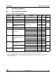
Table 18. Programmable voltage detector characteristics
Symbol Parameter Conditions Min
(1)
Typ Max
(1)
Unit
V
PVD0
PVD threshold 0
Rising edge 2.1 2.18 2.26 V
Falling edge 2 2.08 2.16 V
V
PVD1
PVD threshold 1
Rising edge 2.19 2.28 2.37 V
Falling edge 2.09 2.18 2.27 V
V
PVD2
PVD threshold 2
Rising edge 2.28 2.38 2.48 V
Falling edge 2.18 2.28 2.38 V
V
PVD3
PVD threshold 3
Rising edge 2.38 2.48 2.58 V
Falling edge 2.28 2.38 2.48 V
V
PVD4
PVD threshold 4
Rising edge 2.47 2.58 2.69 V
Falling edge 2.37 2.48 2.59 V