
Datasheet

STM32F050xx Functional overview
Doc ID 023683 Rev 1 21/97
3.13 Inter-integrated circuit interface (I
2
C)
The I
2
C interface (I2C1) can operate in multimaster or slave mode. It can support Standard
mode (up to 100 kbit/s), Fast mode (up to 400 kbit/s) and Fast Mode Plus (up to 1 Mbit/s)
with 20 mA output drive.
It supports 7-bit and 10-bit addressing modes, multiple 7-bit slave addresses (2 addresses,
1 with configurable mask). It also includes programmable analog and digital noise filters.
In addition, I2C1 provides hardware support for SMBUS 2.0 and PMBUS 1.1: ARP
capability, Host notify protocol, hardware CRC (PEC) generation/verification, timeouts
verifications and ALERT protocol management. I2C1 also has a clock domain independent
from the CPU clock, allowing the I2C1 to wake up the MCU from Stop mode on address
match.
The I2C interface can be served by the DMA controller.
3.14 Universal synchronous/asynchronous receiver transmitter
(USART)
The device embeds an universal synchronous/asynchronous receiver transmitters
(USART1), which communicates at speeds of up to 6 Mbit/s.
It provides hardware management of the CTS, RTS and RS485 DE signals, multiprocessor
communication mode, master synchronous communication and single-wire half-duplex
communication mode. It also supports SmartCard communication (ISO 7816), IrDA SIR
ENDEC, LIN Master/Slave capability, auto baud rate feature and has a clock domain
independent from the CPU clock, allowing it to wake up the MCU from Stop mode.
The USART interface can be served by the DMA controller.
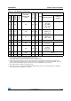
Table 6. Comparison of I2C analog and digital filters
Analog filter Digital filter
Pulse width of
suppressed spikes
≥ 50 ns
Programmable length from 1 to 15
I2C peripheral clocks
Benefits Available in Stop mode
1. Extra filtering capability vs.
standard requirements.
2. Stable length
Drawbacks
Variations depending on
temperature, voltage, process
Wakeup from Stop on address
match is not available when digital
filter is enabled.