
Datasheet


DocID025377 Rev 1 3/14
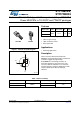
STF7N80K5, STFI7N80K5 Electrical ratings
14
1 Electrical ratings
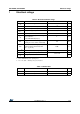
Table 2. Absolute maximum ratings
Symbol Parameter Value Unit
V
GS
Gate- source voltage ± 30 V
I
D
Drain current (continuous) at T
C
= 25 °C 6
(1)
1. Limited by package
A
I
D
Drain current (continuous) at T
C
= 100 °C 3.8
(1)
A
I
DM
(2)
2. Pulse width limited by safe operating area.
Drain current (pulsed) 24
(1)
A
P
TOT
Total dissipation at T
C
= 25 °C 25 W
I
AR
Max current during repetitive or single
pulse avalanche
(pulse width limited by T
jmax
)
2A
E
AS
Single pulse avalanche energy
(starting T
J
= 25 °C, I
D
=I
AS
, V
DD
= 50 V)
88 mJ
V
ISO
Insulation withstand voltage (RMS) from
all three leads to external heat sink
(t=1 s; T
C
=25 °C)
2500 V
dv/dt
(3)
3. I
SD
≤ 6 A, di/dt ≤ 100 A/µs, V
DS(peak)
≤ V
(BR)DSS
Peak diode recovery voltage slope 4.5 V/ns
T
j
Operating junction temperature
-55 to 150
°C
T
stg
Storage temperature °C
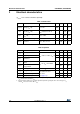
Table 3. Thermal data
Symbol Parameter Value Unit
R
thj-case
Thermal resistance junction-case max 5 °C/W
R
thj-amb
Thermal resistance junction-amb max 62.5 °C/W