
Datasheet
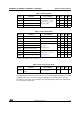


Electrical characteristics STD4N80K5, STF4N80K5, STP4N80K5, STU4N80K5
6/23 DocID025105 Rev 3
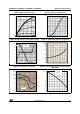
2.1 Electrical characteristics (curves)
Figure 2. Safe operating area for DPAK and
IPAK
Figure 3. Thermal impedance for DPAK and
IPAK
I
D
10
1
0.1
0.1
1
100
V
DS
(V)
10
(A)
Operation in this area is
Limited by max R
DS(on)
10µs
100µs
1ms
10ms
Tj=150°C
Tc=25°C
Single pulse
0.01
AM15986v1
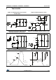
Figure 4. Safe operating area for TO-220FP Figure 5. Thermal impedance for TO-220FP
I
D
10
1
0.1
0.1
1
100
V
DS
(V)
10
(A)
Operation in this area is
Limited by max R
DS(on)
10µs
100µs
1ms
10ms
Tj=150°C
Tc=25°C
Single pulse
0.01
AM15987v1
Figure 6. Safe operating area for TO-220 Figure 7. Thermal impedance for TO-220
I
D
10
1
0.1
0.1
1
100
V
DS
(V)
10
(A)
Operation in this area is
Limited by max R
DS(on)
10µs
100µs
1ms
10ms
Tj=150°C
Tc=25°C
Single pulse
0.01
AM15988v1