
Datasheet

List of figures UM0984
4/25 Doc ID 17812 Rev 2
List of figures
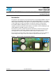
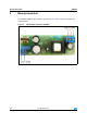
Figure 1. Demonstration board STEVAL-ISA081V1 . . . . . . . . . . . . . . . . . . . . . . . . . . . . . . . . . . . . . . 1
Figure 2. Input/output connection of SMPS . . . . . . . . . . . . . . . . . . . . . . . . . . . . . . . . . . . . . . . . . . . . . 6
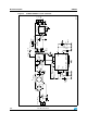
Figure 3. STEVAL-ISA081V1 circuit schematic . . . . . . . . . . . . . . . . . . . . . . . . . . . . . . . . . . . . . . . . . . 8
Figure 4. Transformer construction . . . . . . . . . . . . . . . . . . . . . . . . . . . . . . . . . . . . . . . . . . . . . . . . . . 11
Figure 5. PCB layout - from top side TOP, BOT SMD, BOT copper . . . . . . . . . . . . . . . . . . . . . . . . . 12
Figure 6. Efficiency at 120 VAC and 230 VAC vs. output current . . . . . . . . . . . . . . . . . . . . . . . . . . . 15
Figure 7. Efficiency at full load (1 A) vs. input voltage . . . . . . . . . . . . . . . . . . . . . . . . . . . . . . . . . . . . 16
Figure 8. Standby power vs. input voltage. . . . . . . . . . . . . . . . . . . . . . . . . . . . . . . . . . . . . . . . . . . . . 17
Figure 9. 12 V output load regulation. . . . . . . . . . . . . . . . . . . . . . . . . . . . . . . . . . . . . . . . . . . . . . . . . 18
Figure 10. 3.3 V output load regulation . . . . . . . . . . . . . . . . . . . . . . . . . . . . . . . . . . . . . . . . . . . . . . . . 19
Figure 11. Output voltage at no load vs. the input voltage level . . . . . . . . . . . . . . . . . . . . . . . . . . . . . 19
Figure 12. EMI measurement regarding EN55022 Class 2 - left peak detector,
right AVG detector . . . . . . . . . . . . . . . . . . . . . . . . . . . . . . . . . . . . . . . . . . . . . . . . . . . . . . . 20
Figure 13. Thermal map of the board at 305 V AC on the input - left bottom side, right top side . . . . 21
Figure 14. Thermal map of the board at 85 V AC on the input - left bottom side, right top side . . . . . 21