
Datasheet

UM0984 Measurements
Doc ID 17812 Rev 2 17/25
4.2 Standby
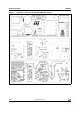
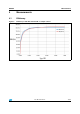
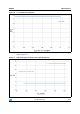
Figure 8. Standby power vs. input voltage
The standby behavior of the board is displayed in Figure 8. The blue line is the standby input
power of the fully assembled board. The red line is the standby input power of the board
without linear regulator L78L33 and with a 15 V Zener diode applied as a bleeder. The
typical input current of L78L33 is 3.5 mA which is approximately 40 mW of load present on
the secondary side.
The standby input power was directly measured by power analyzer NORMA 4000. The
output connection was kept open during the measurement.