
Datasheet

Board description UM0984
10/25 Doc ID 17812 Rev 2
Peak clamp (D1, R2, R3, C3)
This circuit absorbs energy from the voltage spike present after MOSFET turn-off. This
spike is generated by leakage inductance of the transformer. Alternatively, a Transil™-
based peak clamp can be used - for instance PKC-136. The application of this device
allows reducing standby consumption and it can also save some space on the board.
Secondary side (D3, C8, C11, R9, C9, IC2, C10)
The main secondary part is a rectifier consisting of D3 and C8. The C8 capacitor is
stressed by a high level peak current and therefore a low ESR capacitor is used. The
snubber circuit (optional) of D3 consists of C11 and R9. Thanks to the primary
regulation, no additional components are required.
A simple linear regulator to generate 3.3 V on the output can also be implemented. The
regulator (IC2) plays also the role of a bleeder - partly loading the output and keeping
the output voltage below limits at no load. In case IC2 is not assembled, some type of
bleeder (either a Zener diode or resistor) has to be applied in order to limit the
maximum output voltage at no load.
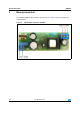
Note: Components C13, DB1 and D3 appear with a suffix “A” on the PCB. This signifies that there
is an assembled alternative package on the board. The functionality of such a component is
the same as the basic component and therefore these components are not indicated in the
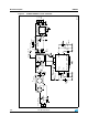
schematic visible in Figure 3.
3.3 Transformer
The transformer construction is designed in order to get good coupling between the auxiliary
and secondary to reach applicable load regulation even when the primary regulation is
used.
The transformer was developed in cooperation with WÜRTH ELEKTRONIK company and is
available under order number 760871131. The transformer specifications are as follows:
● E20/10/6 - 60 kHz, voltage range 85 - 305 VAC
● Core shape E20/10/6
● Core Al 150 nH
● Primary to secondary isolation 4 kV AC
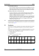
Table 1. Transformer windings
Layer
Start
pin
Stop
pin
Number
of turns
Wire
number
Wire
diameter
(mm)
Wire
material
Inductance
(µH)
Position
1 3 1 96 2 0.2 Cu2l 1394 Primary
2
7, 8, 9,
10
11, 12,
13, 14
10 4 0.3 TeX 15 12 V / 1 A
3 6 5 12 1 0.2 Cu2l 22 14.5 V / aux.