
Datasheet

Electrical characteristics STCS2A
6/18
4 Electrical characteristics
Note: All devices 100 % production tested at T
A
= 25 °C. Limits over the operating temperature
range are guaranteed by design.
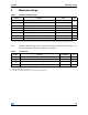
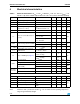
Table 5. Electrical characteristics (V
CC
= 12 V; I
O
= 100 mA; T
J
= -40 °C to 125 °C; V
DRAIN
= 1 V;
C
DRAIN
= 1 µF; C
BYP
= 100 nF typical values are at T
A
= 25°C, unless otherwise specified)
Symbol Parameter Test conditions Min. Typ. Max. Unit
V
CC
Supply voltage range 4.5 40 V
Output current range 1 2000 mA
I
O
Output current R
FB
= 50 mΩ 2A
Regulation (percentage with
respect to V
CC
= 12 V)
V
CC
= 4.5 to 40 V,
I
O
= 100 mA; V
DRAIN
= 1 V
-1 +1 %
V
FB
Feedback voltage I
O
= 0 to 2A 90 100 110 mV
I
CC
Quiescent current (Measured on
V
CC
pin)
On Mode 450 750
µA
Shutdown Mode;
V
CC
= 5 to 12V
1
Shutdown Mode;
V
CC
= 12 to 40V
3
V
DROP
Dropout voltage (V
DRAIN
to GND)
I
O
= 100 mA 0.12 0.16
V
I
O
= 2 A 0.58 0.9
LEAK
DRAIN
Drain leakage current Shutdown; V
DRAIN
= 40 V 10 µA
T
R
/T
F
Rise/Fall time of the current on
PWM transition
C
SLOPE
= 10 nF,
T
J
= -40 °C to 105 °C
800 µs
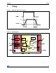
T
D
Delay on PWM signal (Figure 1)
V
PWM
rising, V
CC
= 12 V
C
SLOPE
= floating
3
µs
V
PWM
falling, V
CC
= 12 V
C
SLOPE
= floating
1.2
DISC
Low level voltage I
SINK
= 5 mA 0.2 0.5 V
Leakage current V
DISC
= 5 V 1 µA
Load disconnection threshold
(V
DRAIN
-GND)
DISC Turn-ON 75
mV
DISC Turn-OFF 110
Thermal
Protection
Shutdown temperature 155
°C
Hysteresis 25
Logic inputs (PWM and EN)
V
L
Input low level 0.4 V
V
H
Input high level 1.2 V
EN, PWM leakage current V
EN
= 5 V; V
PWM
= 5 V 2
µAEN input leakage current V
EN
= 40 V 60
PWM input leakage current V
PWM
= 40 V 120