
Datasheet

Application information STCS2A
12/18
8 Application information
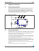
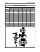
8.1 Reverse polarity protection
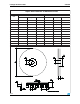
STCS2A must be protected from reverse connection of the supply voltage. Since the current
sunk from V
CC
pin is in the range of 450 µA a small diode connected to V
CC
is able to
protect the chip. Care must be taken for the whole application circuit, especially for the
LEDs, in fact, in case a negative voltage is applied between V
IN
and GND, a negative
voltage will be applied to the LED string that must have a total breakdown voltage higher
than the negative applied voltage in order to avoid any damage.
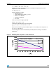
8.2 Thermal considerations
The STCS2A is able to control a LED current up to 2 A and able to sustain a voltage on the
drain pin up to 40 V. Those operating conditions are however limited by thermal constraints.
The poor thermal conduction of epoxy FR4 boards does not permit to benefit of the
outstanding thermal performance of the PowerSO-10.
In any case one way to improve the thermal conduction is the use of large heat spreader
areas at the copper layer of the PC board. This leads to a reduction of thermal resistance to
30 - 36 °C/W for 3 to 6 cm
2
on-board heatsink.
Use of copper-filled through holes on conventional FR4 techniques increases the
metallization and decreases thermal resistance accordingly. Using a configuration with 16
holes under the spreader of the package with a pitch of 1.8 mm and a diameter of 0.7 mm,
the thermal resistance (junction - heatsink) can be reduced to 12 °C/W.
The thermal resistances shown in the Error! Reference source not found. section are the
typical ones.
The power dissipation in the device can be calculated as follow:
Figure 15. Reverse polarity condition
PWM
EN
FB
V
CC
DRAIN
V
IN
+
or similar
BAT46
ENEN
GND
EN
SLOPE
R
SENSE
C
SLOPE
SOURCE
DISC
PWM
EN
FB
V
CC
DRAIN
V
IN
+
or similar
BAT46
ENEN
GND
EN
SLOPE
R
SENSE
C
SLOPE
SOURCE
DISC