
Datasheet


Table Of Contents
- 1 Characteristics
- Table 1. Absolute maximum ratings (Tamb = 25 C)
- Table 2. Thermal resistances
- Figure 1. Electrical characteristics - definitions
- Figure 2. Pulse definition for electrical characteristics
- Table 3. Electrical characteristics - parameter values (Tamb = 25 C)
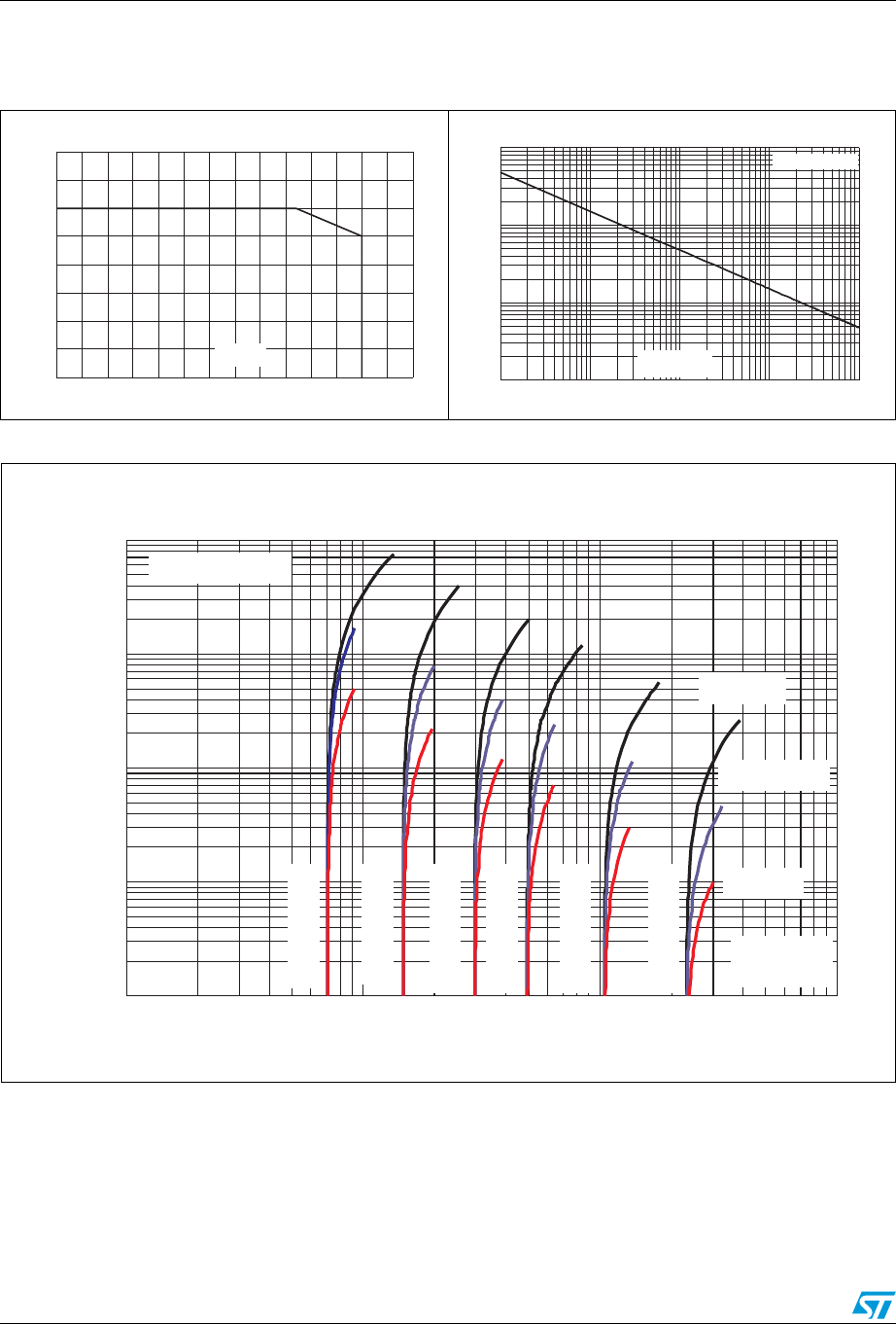
- Figure 3. Peak pulse power dissipation versus initial junction temperature
- Figure 4. Peak pulse power versus exponential pulse duration (Tj initial = 25 C)
- Figure 5. Clamping voltage versus peak pulse current (exponential waveform, maximum values)
- Figure 6. Junction capacitance versus reverse applied voltage for unidirectional types (typical values)
- Figure 7. Junction capacitance versus reverse applied voltage for bidirectional types (typical values)
- Figure 8. Peak forward voltage drop versus peak forward current (typical values)
- Figure 9. Relative variation of thermal impedance, junction to ambient, versus pulse duration
- Figure 10. Thermal resistance junction to ambient versus copper surface under each lead
- Figure 11. Leakage current versus junction temperature (typical values)
- 2 Ordering information scheme
- 3 Package information
- 4 Ordering information
- 5 Revision history
Characteristics SMCJ
4/10 Doc ID 5617 Rev 8
Figure 5. Clamping voltage versus peak pulse current (exponential waveform, maximum values)
Figure 3. Peak pulse power dissipation
versus initial junction temperature
Figure 4. Peak pulse power versus
exponential pulse duration
(T
j
initial = 25 °C)
0
500
1000
1500
2000
0 25 50 75 100 125 150 175
P
pp
(W
)
T
j
(°C)
0.1
1.0
10.0
100.0
1.0E-03 1.0E-02 1.0E-01 1.0E+00 1.0E+01
P
PP
(kW)
T
j
initial = 25 °C
t
P
(ms)
I
PP
(A)
0.1
1.0
10.0
100.0
1000.0
1 10 100 1000
10/1000 µs
T
j
initial=25 °C
8/20 µs
10 ms
SMCJ5.0A
SMCJ12A
SMCJ24A
SMCJ40A
SMCJ85A
SMCJ188A
V
CL
(V)