
User manual


Functional description VL6180X
24/79 DocID026171 Rev 6
The buffer is read via eight 16-bit registers (RESULT__HISTORY_BUFFER_0{0x52} to
RESULT__HISTORY_BUFFER_7{0x60}). The buffer holds the last 16 x 8-bit range or 8 x
16-bit ALS results as shown in Table 9.
Note: Only one data stream (ALS or range) can be buffered at one time. There is no associated
time stamp information.
The clear buffer command is not immediate; it takes effect on the next range or ALS start
command.
The history buffer works independently of interrupt control i.e. the history buffer records all
new samples; its operation is unchanged in threshold and window modes.
2.11 Current consumption
Table 10. gives an overview of current consumption in different operating states.
2.11.1 Ranging current consumption
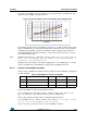
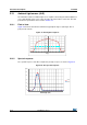
Figure 14. shows typical ranging current consumption of the VL6180X. Current consumption
depends on target distance, target reflectance and sampling rate. The example shown here
is based on default settings and a sampling rate of 10 Hz. The average current consumption
for a 17% reflective target at 50 mm operating at 10 Hz is 1.7 mA. At different sampling rates
Table 9. History buffer
History buffer
Range ALS
(High byte) (Low byte) (Word)
0 Range [15] (newest) Range [14] ALS [7] (newest)
1 Range [13] Range [12] ALS [6]
2 Range [11] Range [10] ALS [5]
3 Range [9] Range [8] ALS [4]
4 Range [7] Range [6] ALS [3]
5 Range [5] Range [4] ALS [2]
6 Range [3] Range [2 ALS [1]
7 Range [1] Range [0] (oldest) ALS [0] (oldest)
Table 10. Typical current consumption in different operating states
Mode Current Conditions
Hardware standby < 1 μA Shutdown (GPIO0 = 0). No I
2
C comms
Software standby < 1 μA After MCU boot. Device ready
ALS 300 μA During integration
Ranging 1.7 mA Average consumption during ranging
(1)
1. 10 Hz sampling rate, 17% reflective target at 50 mm.