
User manual


DocID026171 Rev 6 13/79
VL6180X Functional description
78
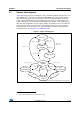
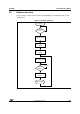
2.1 System state diagram
Figure 8 describes the main operating states of the VL6180X. Hardware standby is the reset
state (GPIO0=0)
(a)
. The device is held in reset until GPIO0 is de-asserted. Note that the
device will not respond to I
2
C communication in this mode. When GPIO0=1, the device
enters software standby after the internal MCU boot sequence has completed. Once in
software standby, ST recommended register initialization settings
(b)
can be applied along
with any required application specific register settings. Thereafter, the host can command
single-shot range or ALS measurements or alternatively program one of the continuous
operating modes where the device uses an internal timer to schedule measurements at
specified intervals. See Section 2.4.3: Interleaved mode.
Figure 8. System state diagram
a. Use of GPIO0 is optional
b. Please contact STMicroelectronics for the latest settings
Power off
Hardware
standby
Software
standby
Range
measurement
ALS
measurement
Continuous
modes
(*)
AVDD on
GPIO0=0
AVDD off
AVDD on
GPIO0=1
GPIO0=1
GPIO0=0
AVDD off
als_start
range_start
done
done
mode=
continuous
startstop
auto
auto
MCU boot
(*) Device is placed in a low power state between measurements