
Data Sheet


AN1012 TIMEKEEPER products
Doc ID 6395 Rev 4 13/33
5.1 TIMEKEEPER
®
register map
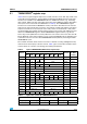
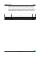
Tabl e 2 shows a typical register map for the seconds, minutes, hours, date, day, month, and
year fields. This information is stored in Binary Coded Decimal (BCD) format. These basic
functions are available on all TIMEKEEPER devices. Additional features (e.g., watchdog
timer, alarms, battery low flag, and a wake-up function) have additional registers allocated to
them (such as those shown for the M48T37V/Y in Ta bl e 2 ). The TIMEKEEPER register
locations are constructed from BiPORT™ memory cells which allow data access from two
sides. The on-chip system clock connects to one side (the system side) and the user data is
output to connections on the other (the user’s side). At one-second intervals, clock pulses
are generated by the oscillator and clock chain structure. The system side updates the new
time in the TIMEKEEPER registers. Each TIMEKEEPER register location (e.g. minutes,
hours, day) is then updated as necessary. When the user wants to write a new time, the “W”
bit (the Write bit) of the control register is reset, causing the BiPORT cells to upload the new
system time. The user accesses the TIMEKEEPER and array data by executing standard
READ/WRITE cycles.
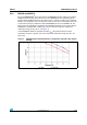
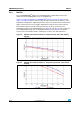
The oscillator and clock chain structure consists of a mixture of analog and digital circuitry,
and account for the majority of the I
BAT
current. Ta ble 3 gives conservative estimates of the
currents drawn as a function of technology and working temperature.
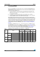
Table 2. Typical TIMEKEEPER (M48T37V/Y) register map
Table 3. Typical I
BAT
current for TIMEKEEPER devices
Address
Data
Function
Range
(in BCD
format)
D7 D6 D5 D4 D3 D2 D1 D0
7FFFh 10 Years Year Year 00-99
7FFEh 0 0 0 10M Month Month 01-12
7FFDh 0 0 10 Date Date Date 01-31
7FFCh 0 FT 0 0 0 Day Day 01-7
7FFBh 0 0 10 Hours Hours Hours 00-23
7FFAh 0 10 Minutes 10 Minutes Minute 00-59
7FF9h ST 10 Seconds Seconds Second 00-59
7FF8h W R S Calibration Control
7FF7h WDS BMB4 BMB3 BMB2 BMB1 BMB0 RB1 RB0 Watch
7FF6h AFE 0 ABE 0 0 0 0 0 Interrupt
7FF5h RPT4 0 AI 10 Date Alarm Date A Date 01-31
7FF4h RPT3 0 AI 10 Hour Alarm Hour A Hour 00-23
7FF3h RPT2 Alarm 10 Minutes Alarm Minutes A Minute 00-59
7FF2h RPT1 Alarm 10 Seconds Alarm Seconds A Second 00-59
7FF1h 1000 Years 100 Years Century 00-99
7FF0h WDF AF 0 BL Z Z Z Z Flags
Typical at 20°C Typical at 70°C
Capacity Technology Array Clock Array Clock
64 Kbit 4T Cell 40 nA 497 nA 511 nA 619 nA