
Datasheet


LCDP1521 Technical information
Doc ID 8627 Rev 4 7/12
various country standards. Taking into account this fact, the actual lightning surge current
flowing through the LCDP is equal to:
I
surge
= V
surge
/ (Rg + Rs)
With:
V
surge
= peak surge voltage imposed by the standard.
Rg = series resistor of the surge generator
Rs = series resistor of the line card (equivalent to PTC + R in Figure 7)
Example: For a line card with 60 Ω of series resistors, which has to be qualified under
GR-1089 Core 1000 V, 10/1000µs surge, the actual current through the LCDP1521 is equal
to:
I
surge
= 1000 / (10 + 60) = 14 A
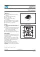
The LCDP1521 is particularly optimized for the new telecom applications such as the fiber in
the loop, the WLL, and the remote central office. In this case the operating voltages are
smaller than in the classic system. This makes the high voltage SLICs particularly suitable.
The schematics of Figure 7 show the topologies most frequently used for these applications.
Figure 7. Protection of high voltage SLICs
LC D Pxxxx
SLIC 1
-Vbat
PTC or Fuse
PTC or Fuse
R
R
Line 1
PTC or Fuse
PTC or Fuse
Line 2
Ring relay 1
RING
TIP
SLIC 2
R
R
Ring relay 2