
Datasheet


DocID023278 Rev 4 53/75
L6480 Programming manual
75
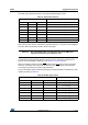
The TCC parameter defines the duration of constant current phase during gate turn-on and
turn-off sequences (Section 6.15 on page 32).
The TBOOST parameter defines the duration of the overboost phase during gate turn-off
(Section 6.15 on page 32).
The WD_EN bit enables the clock source monitoring (Section 6.8.2 on page 27).
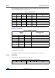
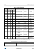
9.1.22 GATECFG2
The GATECFG2 register has the following structure:
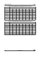
Table 26. TCC parameter
TCC [4…0] Constant current time [ns]
00000 125
00001 250
11100 3625
11101 3750
11110 3750
11111 3750
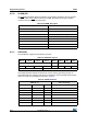
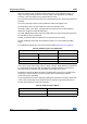
Table 27. TBOOST parameter
TBOOST
[2…0]
Turn-off boost time
[ns]
000 0
001 62.5
(1)
/83.3
(2)
/125
(3)
1. Clock frequency equal to 16 MHz or 32 MHz.
2. Clock frequency equal to 24 MHz.
3. Clock frequency equal to 8 MHz.
0 1 0 125
0 1 1 250
1 0 0 375
1 0 1 500
1 1 0 750
1 1 1 1000
Table 28. GATECFG2 register (voltage mode)
Bit 7 Bit 6 Bit 5 Bit 4 Bit 3 Bit 2 Bit 1 Bit 0
TBLANK TDT