
Datasheet


Programming manual L6480
52/75 DocID023278 Rev 4
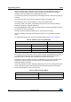
9.1.20 ALARM_EN
The ALARM_EN register allows the selection of which alarm signals are used to generate
the FLAG
output. If the respective bit of the ALARM_EN register is set high, the alarm
condition forces the FLAG
pin output down.
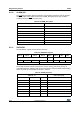
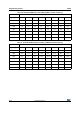
9.1.21 GATECFG1
The GATECFG1 register has the following structure:
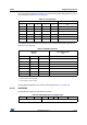
The IGATE parameter selects the sink/source current used by gate driving circuitry to
charge/discharge the respective gate during commutations. Seven possible values ranging
from 4 mA to 96 mA are available, as shown in Table 25.
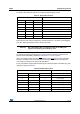
Table 23. ALARM_EN register
ALARM_EN bit Alarm condition
0 (LSB) Overcurrent
1 Thermal shutdown
2 Thermal warning
3UVLO
4 ADC UVLO
5 Stall detection
6 Switch turn-on event
7 (MSB) Command error
Table 24. GATECFG1 register
Bit 15 Bit 14 Bit 13 Bit 12 Bit 11 Bit 10 Bit 9 Bit 8
WD_EN TBOOST
Bit 7 Bit 6 Bit 5 Bit 4 Bit 3 Bit 2 Bit 1 Bit 0
IGATE TCC
Table 25. IGATE parameter
IGATE [2…0} Gate current [mA}
000 4
001 4
010 8
011 16
100 24
101 32
110 64
111 96