
Datasheet

Programming manual L6480
44/75 DocID023278 Rev 4
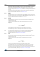
9.1.1 ABS_POS
The ABS_POS register contains the current motor absolute position in agreement with the
selected step mode; the stored value unit is equal to the selected step mode (full, half,
quarter, etc.). The value is in 2's complement format and it ranges from -2
21
to +2
21
-1.
At power-on the register is initialized to “0” (HOME position).
Any attempt to write the register when the motor is running causes the command to be
ignored and the NOTPERF_CMD flag to rise (Section 9.1.24 on page 59).
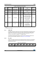
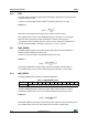
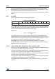
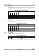
9.1.2 EL_POS
The EL_POS register contains the current electrical position of the motor. The two MSbits
indicate the current step and the other bits indicate the current microstep (expressed in
step/128) within the step.
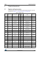
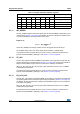
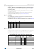
h17 ALARM_EN Alarms enables 8 FF All alarms enabled R, WS
h18 GATECFG1
Gate driver
configuration
11 0
I
gate
= 4 mA, t
CC
= 125 ns, no
boost
R, WH
h19 GATECFG2
Gate driver
configuration
80t
BLANK
= 125 ns, t
DT
= 125 ns R, WH
h1A CONFIG IC configuration 16 2C88
Internal 16 MHz oscillator
(OSCOUT at 2 MHz),
SW event causes HardStop,
motor supply voltage
compensation disabled,
overcurrent shutdown,
V
CC
= 7.5 V,
UVLO threshold low,
f
PWM
= f
OSC
/ 1024
R, WH
h1B STATUS Status 16 XXXX
(2)
High impedance state,
motor stopped,
reverse direction,
all fault flags released
UVLO/Reset flag set
R
1. R: readable, WH: writable, only when outputs are in high impedance, WS: writable only when motor is stopped, WR: always
writable.
2. According to startup conditions.
Table 11. Register map (continued)
Address
[Hex]
Register name Register function
Len.
[bit]
Reset
[Hex]
Reset
value
Remarks
(1)
Table 12. EL_POS register
Bit 8 Bit 7 Bit 6 Bit 5 Bit 4 Bit 3 Bit 2 Bit 1 Bit 0
STEP MICROSTEP