
Datasheet


DocID023278 Rev 4 39/75
L6480 Phase current control
75
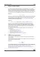
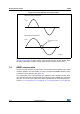
To obtain different current values during acceleration and deceleration phase, two different
final slope values, and consequently two different compensation curves, can be
programmed.
Acceleration compensation curve is applied when the motor runs. No BEMF compensation
is applied when the motor is stopped.
7.5 Motor supply voltage compensation
The sine wave amplitude generated by the PWM modulators is directly proportional to the
motor supply voltage (V
S
). When the motor supply voltage is different from its nominal
value, the motor phases are driven with an incorrect voltage. The L6480 can compensate
motor supply voltage variations in order to avoid this effect.
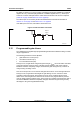
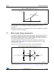
The motor supply voltage should be connected to the integrated ADC input through
a resistor divider in order to obtain V
REG
/2 voltage at the ADCIN pin when V
S
is at its
nominal value (see Figure 18).
The ADC input is sampled at f
S
frequency, which is equal to PWM frequency.
Motor supply voltage compensation can be enabled setting high the EN_VSCOMP bit of the
CONFIG register (seeTable 37 on page 56, Section 9.1.23 on page 54). If the EN_VSCOMP
Figure 17. BEMF compensation curve
$0Y
4QFFE
$PNQFOTBUJPO
WBMVF
*/5@41&&%
45@4-1
'/@4-1@"$$
'/@4-1@%&$
Figure 18. Motor supply voltage compensation circuit
AM12836v1
ADCIN
ADC
5
f
PWM
ADC_OUT
V
S
V
REG
R
A
R
B
V
ADCIN
= V
S
x R
B
/ (R
A
+ R
B
)