
Datasheet


DocID023278 Rev 4 35/75
L6480 Functional description
75
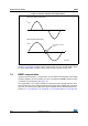
6.19 BUSY/SYNC pin
This pin is an open drain output which can be used as busy flag or synchronization signal
according to the SYNC_EN bit value (STEP_MODE register) (see Section 9.1.19 on page
50).
6.20 FLAG pin
By default, an internal open drain transistor pulls the FLAG pin to ground when at least one
of the following conditions occurs:
Power-up or standby/reset exit
Stall detection on bridge A
Stall detection on bridge B
Overcurrent detection
Thermal warning
Thermal shutdown
UVLO
UVLO on ADC input
Switch turn-on event
Command error.
It is possible to mask one or more alarm conditions by programming the ALARM_EN
register (see Section 9.1.20 on page 52 and Table 23 on page 52). If the corresponding bit
of the ALARM_EN register is low, the alarm condition is masked and it does not cause a
FLAG pin transition; all other actions imposed by alarm conditions are performed anyway. In
case of daisy chain configuration, FLAG pins of different ICs can be or-wired to save host
controller GPIOs.