
Datasheet


Functional description L6480
28/75 DocID023278 Rev 4
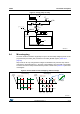
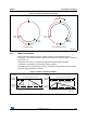
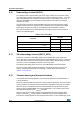
If a direct clock source is used, it must be connected to the OSCIN pin and the OSCOUT pin
supplies the inverted OSCIN signal (see Figure 11).
The L6480 device integrates a clock detection system that resets the device in case of the
failure of the external clock source (direct or crystal/resonator). The monitoring of the clock
source is disabled by default, it can be enabled setting high the WD_EN bit in the
GATECFG1 register (Section 9.1.21 on page 52). When the external clock source is
selected, the device continues to work with the integrated oscillator for t
extosc
milliseconds
and then the clock management system switches to the OSCIN input.
Figure 11. OSCIN and OSCOUT pin configuration
Note: When OSCIN is UNUSED, it should be left floating.
When OSCOUT is UNUSED it should be left floating.
Table 8. CL values according to external oscillator frequency
Crystal/resonator freq.
(1)
C
L
(2)
8 MHz 25 pF (ESR
max
= 80 )
16 MHz 18 pF (ESR
max
= 50 )
24 MHz 15 pF (ESR
max
= 40 )
32 MHz 10 pF (ESR
max
= 40 )
1. First harmonic resonance frequency.
2. Lower ESR value allows driving greater load capacitors.
8186('
26&,1 26&287 26&,1 26&287
26&,1 26&287
0+]
0+]
0+]
([WHUQDORVFLOODWRU
FRQILJXUDWLRQ
([WHUQDOFORFNVRXUFH
FRQILJXUDWLRQ
,QWHUQDORVFLOODWRU
FRQILJXUDWLRQ
ZLWKFORFNJHQHUDWLRQ
26&,1 26&287
,QWHUQDORVFLOODWRU
FRQILJXUDWLRQ
ZLWKRXWFORFNVRXUFH
8186(' 8186('
26&B6(/ [[
26&B6(/ [[
&/ &/
(;7B&/. (;7B&/.
$0Y