L6480 cSPIN™: microstepping motor controller with motion engine and SPI Datasheet - production data Applications Bipolar stepper motor Description The L6480 device, realized in analog mixed signal technology, is an advanced fully integrated solution suitable for driving two-phase bipolar stepper motors with microstepping. HTSSOP38 Features Operating voltage: 7.
Contents L6480 Contents 1 Block diagram . . . . . . . . . . . . . . . . . . . . . . . . . . . . . . . . . . . . . . . . . . . . . . 9 2 Electrical data . . . . . . . . . . . . . . . . . . . . . . . . . . . . . . . . . . . . . . . . . . . . . 10 2.1 Absolute maximum ratings . . . . . . . . . . . . . . . . . . . . . . . . . . . . . . . . . . . . 10 2.2 Recommended operating conditions . . . . . . . . . . . . . . . . . . . . . . . . . . . . .11 2.3 Thermal data . . . . . . . . . . . . . . . . . . . .
L6480 7 Contents 6.10 Undervoltage lockout (UVLO) . . . . . . . . . . . . . . . . . . . . . . . . . . . . . . . . . 30 6.11 VS undervoltage lockout (UVLO_ADC) . . . . . . . . . . . . . . . . . . . . . . . . . . 30 6.12 Thermal warning and thermal shutdown . . . . . . . . . . . . . . . . . . . . . . . . . 30 6.13 Reset and standby . . . . . . . . . . . . . . . . . . . . . . . . . . . . . . . . . . . . . . . . . . 31 6.14 External switch (SW pin) . . . . . . . . . . . . . . . . . . . . . . . . . .
Contents L6480 9.2 4/75 9.1.12 ST_SLP . . . . . . . . . . . . . . . . . . . . . . . . . . . . . . . . . . . . . . . . . . . . . . . . . 48 9.1.13 FN_SLP_ACC . . . . . . . . . . . . . . . . . . . . . . . . . . . . . . . . . . . . . . . . . . . . 48 9.1.14 FN_SLP_DEC . . . . . . . . . . . . . . . . . . . . . . . . . . . . . . . . . . . . . . . . . . . . 49 9.1.15 K_THERM . . . . . . . . . . . . . . . . . . . . . . . . . . . . . . . . . . . . . . . . . . . . . . . 49 9.1.16 ADC_OUT . . . . . . . .
L6480 Contents 10 Package information . . . . . . . . . . . . . . . . . . . . . . . . . . . . . . . . . . . . . . . . 72 11 Revision history . . . . . . . . . . . . . . . . . . . . . . . . . . . . . . . . . . . . . . . . . . .
List of tables L6480 List of tables Table 1. Table 2. Table 3. Table 4. Table 5. Table 6. Table 7. Table 8. Table 9. Table 10. Table 11. Table 12. Table 13. Table 14. Table 15. Table 16. Table 17. Table 18. Table 19. Table 20. Table 21. Table 22. Table 23. Table 24. Table 25. Table 26. Table 27. Table 28. Table 29. Table 30. Table 31. Table 32. Table 33. Table 34. Table 35. Table 36. Table 37. Table 38. Table 39. Table 40. Table 41. Table 42. Table 43. Table 44. Table 45. Table 46. Table 47. Table 48.
L6480 Table 49. Table 50. Table 51. Table 52. Table 53. Table 54. Table 55. Table 56. Table 57. Table 58. Table 59. Table 60. Table 61. Table 62. Table 63. Table 64. Table 65. Table 66. Table 67. Table 68. Table 69. List of tables Nop command structure . . . . . . . . . . . . . . . . . . . . . . . . . . . . . . . . . . . . . . . . . . . . . . . . . . . 64 SetParam command structure . . . . . . . . . . . . . . . . . . . . . . . . . . . . . . . . . . . . . . . . . . . . . . 64 GetParam command structure . .
List of figures L6480 List of figures Figure 1. Figure 2. Figure 3. Figure 4. Figure 5. Figure 6. Figure 7. Figure 8. Figure 9. Figure 10. Figure 11. Figure 12. Figure 13. Figure 14. Figure 15. Figure 16. Figure 17. Figure 18. Figure 19. Figure 20. Figure 21. Figure 22. Figure 23. Figure 24. Figure 25. 8/75 Block diagram . . . . . . . . . . . . . . . . . . . . . . . . . . . . . . . . . . . . . . . . . . . . . . . . . . . . . . . . . . . . 9 Pin connection (top view) . . . . . . . . . . . . . . . . . . .
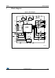
L6480 Block diagram Figure 1. Block diagram 965(* 9ROWDJH 5HJ $'& $'&,1 9&&5(* 9&& 9&& 9ROWDJH 5HJ 95(* 95(* &3 9%227 &KDUJH SXPS 96 9%227 +9*$ 9&& 7HPSHUDWXUH VHQVLQJ 287$ 9%227 9GG 9'' &. 6'2 /9*$ +9*$ 9&& &6 287$ 63, 1 Block diagram /9*$ &25( /2*,& 6', 9%227 67%< 5(6(7 +9*% 9&& 2YHUFXUUHQW GHWHFWLRQ )/$* 287% /9*% 9%227 %86< 6<1& 0+] 2VFLOODWRU 9&& 67&.
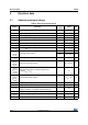
Electrical data L6480 2 Electrical data 2.1 Absolute maximum ratings Table 2. Absolute maximum ratings Symbol Parameter Test condition Value Unit V VDD Logic interface supply voltage 5.5 VREG Logic supply voltage 3.
L6480 2.2 Electrical data Recommended operating conditions Table 3. Recommended operating conditions Symbol Parameter VDD Logic interface supply voltage VREG Logic supply voltage VS Motor supply voltage VSREG VCC VCCREG VADC 2.3 Test condition Min. 3.3 V logic outputs Typ. Max. 3.3 5 V logic outputs Unit V 5 3.
Electrical characteristics 3 L6480 Electrical characteristics VS = 48 V; VCC= 7.5 V; Tj = 25 °C, unless otherwise specified. Table 5. Electrical characteristics Symbol Parameter Test condition Min. Typ. Max. Unit UVLO_VAL set high(1) 9.9 10.4 10.9 V UVLO_VAL set low(1) 6.5 6.9 7.3 V 9.5 10 10.5 V 5.9 6.3 6.7 V UVLO_VAL set high 8.6 9.2 9.8 V UVLO_VAL set low(1) 5.7 6 6.3 V UVLO_VAL set high(1) 8.2 8.8 9.5 V UVLO_VAL set low 5.3 5.5 5.
L6480 Electrical characteristics Table 5. Electrical characteristics (continued) Symbol Parameter RpumpLS Charge pump low-side RDS(ON) resistance 10 Average boot current 2.6 mA Iboot Test condition Min. Typ. Max. Unit Gate driver outputs IGATE,Sink IGATE,Source IOB Programmable high-side and low-side gate sink current Programmable high-side and low-side gate source current VS = 38 V VHVGX - VOUTX > 3 V VLVGX > 3 V VS = 38 V VBOOTX - VHVGX > 3.5 V VCC-VLVGX > 3.
Electrical characteristics L6480 Table 5. Electrical characteristics (continued) Symbol SRgate Parameter Test condition Gate driver output slew rate Min. Typ. IGATE= 96 mA VCC = 15 V CGATE = 15 nF 6 TDT = '00000' 125 TDT = ’11111’ 4000 TBLANK = '000' 125 TBLANK = ’111’ 1000 Max.
L6480 Electrical characteristics Table 5. Electrical characteristics (continued) Symbol Parameter Test condition Min. Typ. Max.
Electrical characteristics L6480 Table 5. Electrical characteristics (continued) Symbol Parameter Test condition Min. Typ. Max. Unit Standby ISTBY Standby mode supply current (VSREG pin) ISTBY,vreg Standby mode supply current (VREG pin) tSTBY,min tlogicwu tcpwu VCC = VCCREG = 7.5 V VSREG = 48 V 42 µA VCC = VCCREG = 7.5 V VSREG = 18 V 37.5 6 µA Minimum standby time 0.
L6480 4 Pin connection Pin connection Figure 2. Pin connection (top view) /9*$ /9*$ 287$ 287$ +9*$ 1& 3*1' $'&,1 67%< 5(6(7 96 6: +9*$ (3$' 9%227 67&. 3*1' )/$* &3 %86< 6<1& 9&& '*1' 9&&5(* 6'2 965(* 9'',2 95(* 6', 26&,1 &. 26&287 &6 $*1' 3*1' +9*% +9*% 287% 287% /9*% /9*% $0 Y Pin list Table 6. Pin description No.
Pin connection L6480 Table 6. Pin description (continued) No. Name Type Function 6 VS Power supply Motor voltage 3 HVGA1 Power output High-side half-bridge A1 gate driver output.
L6480 Typical applications 5 Typical applications Table 7. Typical application values Name Value CVSPOL 220 µF CVS 220 nF CBOOT 470 nF CFLY 47 nF CVSREG 100 nF CVCC 470 nF CVCCREG 100 nF CVREG 100 nF CVREGPOL 22 µF CVDD 100 nF D1 Charge pump diodes Q1, Q2, Q3, Q4, Q5, Q6, Q7, Q8 STD25NF10 RPU 39 k RA 1.8 k (VS = 85 V) RB 91 k (VS = 85 V) Figure 3.
Functional description L6480 6 Functional description 6.1 Device power-up During power-up, the device is under reset (all logic IOs disabled and power bridges in high impedance state) until the following conditions are satisfied: VCC is greater than VCCthOn VBOOT - VS is greater than VBOOTthOn VREG is greater than VREGthOn Internal oscillator is operative STBY/RESET input is forced high.
L6480 Functional description Figure 4. Charge pump circuitry 9' 96 9&3 &%227 96 ' 96 9&3 7' 7' &)/< 9%227 ' &3 9&3 WR KLJK VLGH JDWH GULYHUV 9'' I3803 &KDUJH SXPS RVFLOODWRU $0 Y 6.4 Microstepping The driver is able to divide the single step into up to 128 microsteps. Stepping mode can be programmed by the STEP_SEL parameter in the STEP_MODE register (Table 20 on page 50). Step mode can be only changed when bridges are disabled.
Functional description L6480 Automatic Full-step and Boost modes When motor speed is greater than a programmable full-step speed threshold, the L6480 switches automatically to Full-step mode; the driving mode returns to microstepping when motor speed decreases below the full-step speed threshold. The switching between the microstepping and Full-step mode and vice-versa is always performed at an electrical position multiple of /4 (Figure 6 and Figure 7).
L6480 Functional description Figure 7. Automatic Full-step switching in Boost mode Vpeak Phase A Vpeak Phase B Full-Step Microstepping (2N+1) x π /4 Microstepping (2N+1) x π/4 AM12850v1 6.5 Absolute position counter An internal 22-bit register (ABS_POS) records all the motor motions according to the selected step mode; the stored value unit is equal to the selected step mode (full, half, quarter, etc.). The position range is from -221 to +221-1 steps (see Section 9.1.1 on page 44). 6.
Functional description 6.7 L6480 Motor control commands The L6480 can accept different types of commands: constant speed commands (Run, GoUntil, ReleaseSW) absolute positioning commands (GoTo, GoTo_DIR, GoHome, GoMark) motion commands (Move) stop commands (SoftStop, HardStop, SoftHiz, HardHiz). For detailed command descriptions refer to Section 9.2 on page 62. 6.7.
L6480 Functional description Figure 9. Positioning command examples )RUZDUG GLUHFWLRQ 3UHVHQW SRVLWLRQ 3UHVHQW SRVLWLRQ 7DUJHW SRVLWLRQ 7DUJHW SRVLWLRQ *R7RB',5 7DUJHW SRV ): *R7R 7DUJHW SRV $0 Y 6.7.3 Motion commands Motion commands produce a motion in order to perform a user-defined number of microsteps in a user-defined direction that are sent to the device together with the command (see Figure 10).
Functional description 6.7.4 L6480 Stop commands A stop command forces the motor to stop. Stop commands can be sent anytime. The SoftStop command causes the motor to decelerate with a programmed deceleration value until MIN_SPEED value is reached and then stops the motor keeping the rotor position (a holding torque is applied). The HardStop command stops the motor instantly, ignoring deceleration constraints and keeping the rotor position (a holding torque is applied).
L6480 Functional description The ReleaseSW command makes the motor run at a programmed minimum speed until the SW input is forced high (rising edge). When this event occurs, one of the following actions can be performed: ABS_POS register is set to zero (home position) and the motor immediately stops (as a HardStop command) ABS_POS register value is stored in the MARK register and the motor immediately stops (as a HardStop command).
Functional description L6480 Table 8. CL values according to external oscillator frequency Crystal/resonator freq. (1) CL (2) 8 MHz 25 pF (ESRmax = 80 ) 16 MHz 18 pF (ESRmax = 50 ) 24 MHz 15 pF (ESRmax = 40 ) 32 MHz 10 pF (ESRmax = 40 ) 1. First harmonic resonance frequency. 2. Lower ESR value allows driving greater load capacitors. If a direct clock source is used, it must be connected to the OSCIN pin and the OSCOUT pin supplies the inverted OSCIN signal (see Figure 11).
L6480 6.9 Functional description Overcurrent detection The L6480 measures the load current of each half-bridge sensing the VDS voltage of all the Power MOSFETs (Figure 12). When any of the VDS voltages rise over the programmed threshold, the OCD flag in the STATUS register is forced low until the event expires and a GetStatus command is sent to the device (Section 9.1.24 on page 59 and Section 9.2.20 on page 71).
Functional description 6.10 L6480 Undervoltage lockout (UVLO) The L6480 provides a programmable gate driver supply voltage UVLO protection. When one of the supply voltages of the gate driver (VCC for the low sides and VBOOT - VS for the high sides) falls below the respective turn-off threshold, an undervoltage event occurs. In this case, all MOSFETs are immediately turned off and the UVLO flag in the STATUS register is forced low.
L6480 Functional description active (if supplied). The thermal shutdown condition only expires when the temperature goes below Tj(SD)ON. The thermal condition of the device is shown by TH_STATUS bits in the STATUS register (Table 10). Table 10.
Functional description L6480 By default, a switch turn-on event causes a HardStop interrupt (SW_MODE bit of CONFIG register set to ‘0’). Otherwise (SW_MODE bit of CONFIG register set to ‘1’), switch input events do not cause interrupts and the switch status information is at the user’s disposal (Table 32 on page 55 and Section 9.1.24 on page 59). The switch input can be used by GoUntil and ReleaseSW commands as described in Section 9.2.10 on page 67 and Section 9.2.11 on page 68.
L6480 Functional description Figure 14. Gate driving currents W W *DWH FKDUJHG W *DWH GLVFKDUJHG 2% && ,2% && ,JDWH ,JDWH *DWH &XUUHQW *DWH WXUQ RII *DWH WXUQ RQ The gate current can be set to one of the following values: 4, 8, 16, 24, 32, 64 and 96 mA through the IGATE parameter in the GATECFG1 register (see Section 9.1.21 on page 52). Controlled current time can be programmed within range from 125 ns to 3.75 s with a resolution of 125 ns (TCC parameter in GATECFG1 register) (see Section 9.
Functional description 6.18 L6480 Supply management and internal voltage regulators The L6480 integrates two linear voltage regulators: the first one can be used to obtain gate driver supply starting from a higher voltage (e.g. the motor supply one). Its output voltage can be set to 7.5 V or 15 V according to the VCCVAL bit value (CONFIG register). The second linear voltage regulator can be used to obtain the 3.3 V logic supply voltage.
L6480 6.19 Functional description BUSY/SYNC pin This pin is an open drain output which can be used as busy flag or synchronization signal according to the SYNC_EN bit value (STEP_MODE register) (see Section 9.1.19 on page 50). 6.
Phase current control 7 L6480 Phase current control The L6480 controls the phase current applying a sinusoidal voltage to motor windings. Phase current amplitude is not directly controlled but depends on phase voltage amplitude, load torque, motor electrical characteristics and rotation speed. Sine wave amplitude is proportional to the motor supply voltage multiplied by a coefficient (KVAL).
L6480 7.2 Phase current control Sensorless stall detection The L6480 is able to detect a motor stall caused by an excessive load torque. When the motor is driven using the voltage mode approach, a stall condition corresponds to an unexpected increase of the phase current. Imposing a current threshold slightly above the operative current, it is possible to detect the stall condition without speed or position sensors.
Phase current control L6480 Figure 16. Current distortion and compensation :LWKRXW ORZ VSHHG RSWLPL]D]LRQ ,SKDVH :LWK ORZ VSHHG RSWLPL]D]LRQ ,SKDVH &XUUHQW GLVWRUWLRQ LV KHDYLO\ UHGXFHG $0 Y The optimization can be enabled setting high the LSPD_OPT bit in the MIN_SPEED register (Section 9.1.8 on page 46) and is active in a speed range from zero to MIN_SPEED. When low speed optimization is enabled, speed profile minimum speed is forced to zero. 7.
L6480 Phase current control Figure 17. BEMF compensation curve $PNQFOTBUJPO WBMVF '/@4-1@"$$ '/@4-1@%&$ 45@4-1 4QFFE */5@41&&% $0 Y To obtain different current values during acceleration and deceleration phase, two different final slope values, and consequently two different compensation curves, can be programmed. Acceleration compensation curve is applied when the motor runs. No BEMF compensation is applied when the motor is stopped. 7.
Phase current control L6480 bit is low, the compensation is disabled and the internal analog to digital converter is at the user’s disposal; the sampling rate is always equal to PWM frequency. 7.6 Winding resistance thermal drift compensation The higher the winding resistance the greater the voltage to be applied in order to obtain the same phase current. The L6480 integrates a register (K_THERM) which can be used to compensate phase resistance increment due to temperature rising.
L6480 Serial interface 8 Serial interface The integrated 8-bit serial peripheral interface (SPI) is used for a synchronous serial communication between the host microprocessor (always master) and the L6480 (always slave). The SPI uses chip select (CS), serial clock (CK), serial data input (SDI) and serial data output (SDO) pins. When CS is high the device is unselected and the SDO line is inactive (high impedance). The communication starts when CS is forced low.
Serial interface L6480 Figure 20. Daisy chain configuration '(9 &6 &6 &. &. +2676'2 0 6',0 6', 6'2 '(9 &6 &. +267 63, VLJQDOV 6', 6'2 &6 6'20 %\WH 1 %\WH 1 %\WH %\WH 1 6',0 %\WH 1 %\WH 1 %\WH %\WH 1 '(9 1 &6 &.
L6480 Programming manual 9 Programming manual 9.1 Register and flag description The following section shows the user registers available (detailed description in respective paragraphs from Section 9.1.1 on page 44 to Section 9.1.24 on page 59): Table 11. Register map Address [Hex] Register name Register function Current position Len.
Programming manual L6480 Table 11. Register map (continued) Register name Register function Len.
L6480 Programming manual When the EL_POS register is written by the user the new electrical position is instantly imposed. When the EL_POS register is written, its value must be masked in order to match with the step mode selected in the STEP_MODE register in order to avoid a wrong microstep value generation (Section 9.1.19); otherwise the resulting microstep sequence is incorrect.
Programming manual 9.1.6 L6480 DEC The DEC register contains the speed profile deceleration expressed in step/tick2 (format unsigned fixed point 0.40). In order to convert the DEC value in step/s2 the following formula can be used: Equation 6 – 40 DEC 2 2 step/s = ---------------------------2 tick where DEC is the integer number stored in the register and tick is 250 ns. The available range is from 14.55to 59590 step/s2 with a resolution of 14.55 step/s2.
L6480 Programming manual When the LSPD_OPT bit is set high, low speed optimization feature is enabled and the MIN_SPEED value indicates the speed threshold below which the compensation works. In this case the minimum speed of the speed profile is set to zero. Any attempt to write the register when the motor is running causes the NOTPERF_CMD flag to rise. 9.1.9 FS_SPD The FS_SPD register contains the following parameters: Table 14.
Programming manual L6480 Table 15. Voltage amplitude regulation registers KVAL_X [7…0] 9.1.11 Output voltage 0 0 0 0 0 0 0 1 VS x (1/256) … 0 … 0 … 0 … 0 … 0 … 0 … 0 … 0 … 0 1 1 1 1 1 1 1 0 VS x (254/256) 1 1 1 1 1 1 1 1 VS x (255/256) INT_SPEED The INT_SPEED register contains the speed value at which the BEMF compensation curve changes slope (Section 7.4 on page 38 for details).
L6480 9.1.14 Programming manual FN_SLP_DEC The FN_SLP_DEC register contains the BEMF compensation curve slope that is used when the speed is greater than the intersect speed during deceleration (Section 7.4 on page 38 for details). Its value is expressed in s/step and the available range is from 0 to 0.004 with a resolution of 0.000015. When ST_SLP, FN_SLP_ACC and FN_SLP_DEC parameters are set to zero, no BEMF compensation is performed.
Programming manual 9.1.17 L6480 OCD_TH The OCD_TH register contains the overcurrent threshold value (Section 6.9 on page 29 for details). The available range is from 31.25 mV to 1 V, steps of 31.25 mV, as shown in Table 18. Table 18. Overcurrent detection threshold OCD_TH [4…0] 9.1.18 Overcurrent detection threshold 0 0 0 0 0 31.25 mV 0 0 0 0 1 62.5 mV … … … … … … 1 1 1 1 0 968.75 mV 1 1 1 1 1 1V STALL_TH The STALL_TH register contains the stall detection threshold value.
L6480 Programming manual The STEP_SEL parameter selects one of eight possible stepping modes: Table 21. Step mode selection STEP_SEL[2…0] Step mode 0 0 0 Full-step 0 0 1 Half-step 0 1 0 1/4 microstep 0 1 1 1/8 microstep 1 0 0 1/16 microstep 1 0 1 1/32 microstep 1 1 0 1/64 microstep 1 1 1 1/128 microstep Every time the step mode is changed, the electrical position (i.e. the point of microstepping sine wave that is generated) is reset to the first microstep.
Programming manual 9.1.20 L6480 ALARM_EN The ALARM_EN register allows the selection of which alarm signals are used to generate the FLAG output. If the respective bit of the ALARM_EN register is set high, the alarm condition forces the FLAG pin output down. Table 23. ALARM_EN register 9.1.
L6480 Programming manual The TCC parameter defines the duration of constant current phase during gate turn-on and turn-off sequences (Section 6.15 on page 32). Table 26. TCC parameter TCC [4…0] Constant current time [ns] 0 0 0 0 0 125 0 0 0 0 1 250 1 1 1 0 0 3625 1 1 1 0 1 3750 1 1 1 1 0 3750 1 1 1 1 1 3750 The TBOOST parameter defines the duration of the overboost phase during gate turn-off (Section 6.15 on page 32). Table 27.
Programming manual L6480 The TDT parameter defines the deadtime duration between the gate turn-off and the opposite gate turn-on sequences (Section 6.16 on page 33). Table 29. TDT parameter TDT [4…0] Deadtime [ns] 0 0 0 0 0 125 0 0 0 0 1 250 1 1 1 1 0 3875 1 1 1 1 1 4000 The TBLANK parameter defines the duration of the blanking of the current sensing comparators (stall detection and overcurrent) after each commutation (Section 6.16 on page 33). Table 30.
L6480 Programming manual The OSC_SEL and EXT_CLK bits set the system clock source: Table 32.
Programming manual L6480 The OC_SD bit sets if an overcurrent event causes or not the bridges to turn off; the OCD flag in the status register is forced low anyway: Table 34. Overcurrent event OC_SD Overcurrent event 1 Bridges shut down 0 Bridges do not shut down The VCCVAL bit sets the internal VCC regulator output voltage. Table 35. Programmable VCC regulator output voltage VCCVAL VCC voltage 0 7.5 V 1 15 V The UVLOVAL bit sets the UVLO protection thresholds. Table 36.
L6480 Programming manual The F_PWM_INT bits set the integer division factor of PWM frequency generation. Table 38. PWM frequency: integer division factor F_PWM_INT [2…0] Integer division factor 0 0 0 1 0 0 1 2 0 1 0 3 0 1 1 4 1 0 0 5 1 0 1 6 1 1 0 7 1 1 1 7 The F_PWM_DEC bits set the multiplication factor of PWM frequency generation. Table 39. PWM frequency: multiplication factor F_PWM_DEC [2…0] Multiplication factor 0 0 0 0.625 0 0 1 0.75 0 1 0 0.
Programming manual L6480 Table 40. Available PWM frequencies [kHz]: 8-MHz oscillator frequency F_PWM_DEC F_PWM_INT 000 001 010 011 100 101 110 111 000 9.8 11.7 13.7 15.6 19.5 23.4 27.3 31.3 001 4.9 5.9 6.8 7.8 9.8 11.7 13.7 15.6 010 3.3 3.9 4.6 5.2 6.5 7.8 9.1 10.4 011 2.4 2.9 3.4 3.9 4.9 5.9 6.8 7.8 100 2.0 2.3 2.7 3.1 3.9 4.7 5.5 6.3 101 1.6 2.0 2.3 2.6 3.3 3.9 4.6 5.2 110 1.4 1.7 2.0 2.2 2.8 3.3 3.9 4.5 Table 41.
L6480 Programming manual Table 42. Available PWM frequencies [kHz]: 24-MHz oscillator frequency F_PWM_DEC F_PWM_INT 000 001 010 011 100 101 110 111 000 29.3 35.2 41.0 46.9 58.6 70.3 82.0 93.8 001 14.6 17.6 20.5 23.4 29.3 35.2 41.0 46.9 010 9.8 11.7 13.7 15.6 19.5 23.4 27.3 31.3 011 7.3 8.8 10.3 11.7 14.6 17.6 20.5 23.4 100 5.9 7.0 8.2 9.4 11.7 14.1 16.4 18.8 101 4.9 5.9 6.8 7.8 9.8 11.7 13.7 15.6 110 4.2 5.0 5.9 6.7 8.4 10.0 11.7 13.
Programming manual L6480 When the HiZ flag is high it indicates that the bridges are in high impedance state. Any motion command causes the device to exit from High Z state (HardStop and SoftStop included), unless error flags forcing a High Z state are active. The UVLO flag is active low and is set by an undervoltage lockout or reset events (power-up included). The UVLO_ADC flag is active low and indicates an ADC undervoltage event. The OCD flag is active low and indicates an overcurrent detection event.
L6480 Programming manual MOT_STATUS indicates the current motor status: Table 47. STATUS register MOT_STATE bits MOT_STATUS Motor status 0 0 Stopped 0 1 Acceleration 1 0 Deceleration 1 1 Constant speed Any attempt to write to the register causes the command to be ignored and the NOTPERF_CMD to rise (Section 9.1.24 on page 59).
Programming manual 9.2 L6480 Application commands The commands summary is given in Table 48. Table 48.
L6480 Programming manual 9.2.1 Command management The host microcontroller can control motor motion and configure the L6480 through a complete set of commands. All commands are composed by a single byte. After the command byte, some bytes of arguments should be needed (see Figure 21). Argument length can vary from 1 to 3 bytes. Figure 21.
Programming manual 9.2.2 L6480 Nop Table 49. Nop command structure Bit 7 Bit 6 Bit 5 Bit 4 Bit 3 Bit 2 Bit 1 Bit 0 0 0 0 0 0 0 0 0 From host Nothing is performed. 9.2.3 SetParam (PARAM, VALUE) Table 50.
L6480 Programming manual This command reads the current PARAM register value; PARAM is the respective register address listed in Table 11 on page 43. The command response is the current value of the register (most significant byte first). The number of bytes composing the command response depends on the length of the target register (see Table 11). The returned value is the register one at the moment of GetParam command decoding.
Programming manual L6480 Events that cause bridges to be forced into high impedance state (overtemperature, overcurrent, etc.) do not cause the device to leave Step-clock mode. The StepClock command does not force the BUSY flag low. This command can only be given when the motor is stopped. If a motion is in progress, the motor should be stopped and it is then possible to send a StepClock command.
L6480 Programming manual Any attempt to perform a GoTo command when a previous command is under execution (BUSY low) causes the command to be ignored and the NOTPERF_CMD flag to rise (Section 9.1.24 on page 59). 9.2.9 GoTo_DIR (DIR, ABS_POS) Table 56.
Programming manual L6480 If the SW_MODE bit of the CONFIG register is set low, the external switch turn-on event causes a HardStop interrupt instead of the SoftStop one (Section 6.14 and Section 9.1.23 on page 54). This command keeps the BUSY flag low until the switch turn-on event occurs and the motor is stopped. This command can be given anytime and is immediately executed. 9.2.11 ReleaseSW (ACT, DIR) Table 58.
L6480 Programming manual The GoMark command produces a motion to the MARK position performing the minimum path. Note that, this command is equivalent to the “GoTo (MARK)” command. If a motor direction is mandatory, the GoTo_DIR command must be used. The GoMark command keeps the BUSY flag low until the MARK position is reached. This command can be given only when the previous motion command has been completed (BUSY flag released).
Programming manual 9.2.17 L6480 HardStop Table 64. HardStop command structure Bit 7 Bit 6 Bit 5 Bit 4 Bit 3 Bit 2 Bit 1 Bit 0 1 0 1 1 1 0 0 0 From host The HardStop command causes an immediate motor stop with infinite deceleration. When the motor is in high impedance state, a HardStop command forces the bridges to exit high impedance state; no motion is performed. This command can be given anytime and is immediately executed.
L6480 9.2.20 Programming manual GetStatus Table 67. GetStatus command structure Bit 7 Bit 6 Bit 5 Bit 4 Bit 3 Bit 2 Bit 1 Bit 0 1 1 0 1 0 0 0 0 From host STATUS MSByte To host STATUS LSByte To host The GetStatus command returns the Status register value. The GetStatus command resets the STATUS register warning flags. The command forces the system to exit from any error state. The GetStatus command DOES NOT reset the HiZ flag.
Package information 10 L6480 Package information In order to meet environmental requirements, ST offers these devices in different grades of ECOPACK® packages, depending on their level of environmental compliance. ECOPACK specifications, grade definitions and product status are available at: www.st.com. ECOPACK is an ST trademark. Figure 24. HTSSOP38 package outline ( ( F H ' PP $ $ 3 E $ / 3 Table 68. HTSSOP38 mechanical data Dimensions (mm) Symbol Min.
L6480 Package information Figure 25.
Revision history 11 L6480 Revision history Table 69. Document revision history Date Revision 13-Jun-2012 1 Initial release. 04-Oct-2012 2 Updated Table 2, Table 5, Table 6, Table 9, Table 31, Table 36. Update Figure 8, Figure 9, Figure 10. Minor text changes. 19-Dec-2012 3 Changed the title. Inserted footnote in Table 2 and in Table 4. Updated Table 18 and Table 19. 4 Updated Section 6.3, (replaced “integrated MOSFETs” by “gate drivers”). Updated Section 6.9 to Section 6.13, Section 7.
L6480 Please Read Carefully: Information in this document is provided solely in connection with ST products. STMicroelectronics NV and its subsidiaries (“ST”) reserve the right to make changes, corrections, modifications or improvements, to this document, and the products and services described herein at any time, without notice. All ST products are sold pursuant to ST’s terms and conditions of sale.