
Datasheet

Characteristics HDMI05-CL02F3
2/9 Doc ID 15516 Rev 2
1 Characteristics
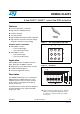
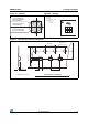
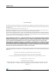
Figure 3. Electrical characteristics (definitions)
Table 1. Absolute maximum ratings (T
amb
= 25 °C)
Symbol Parameter Value Unit
V
PP
External pins (A1, A2, A3, B3 and C3):
ESD IEC 61000-4-2, level 4 - air discharge
ESD IEC 61000-4-2, level 4 - contact discharge
Internal pins (B1, C1):
ESD IEC 61000-4-2, level 1 - air discharge
ESD IEC 61000-4-2, level 1 - contact discharge
15
8
2
2
kV
Pd Line resistance power dissipation at 70 °C 60 mW
T
op
Operating temperature range -30 to + 85 °C
T
stg
Storage temperature range -55 to + 150 °C
Table 2. Electrical characteristics (T
amb
= 25 °C)
Symbol Test condition Min. Typ. Max. Unit
V
BR
I
R
= 1 mA 6 20 V
I
RM
V
RM
= 3 V per line 50 200 nA
R
1
, R
2
1575 1750 1925 Ω
R
3
80 100 120 kΩ
R
4
22 27 32 kΩ
C
line
V
line
= 0 V, V
osc
= 30 mV, F = 1 MHz
CEC to GND with R
PU2
not connected
SCL and SDA to GND with R
PU
not connected
(measured under zero light conditions)
14
24
17
29 pF
C
line
(1)
1. This is the line capacitance seen by the data signals in the application conditions
V
line
= 0 V, V
osc
= 30 mV, F = 1 MHz
CEC, SCL and SDA to GND with R
PU
and R
PU2
grounded
(measured under zero light conditions)
10 12 pF
I
V
I
F
I
RM
I
R
I
PP
V
RM
V
F
V
BR
V
CL
Slope = 1/Rd
Symbol Parameter
V = Breakdown voltage
I = Leakage current @ V
V = Stand-off voltage
V = Clamping voltage
R = Dynamic impedance
I = Peak pulse current
I = Breakdown current
T = Voltage temperature coefficient
V = Forward voltage drop
BR
RM RM
RM
CL
d
PP
R
F
α
C = Line capacitance
=
line
R Series resistance between Input
I/O