
User's Manual
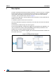
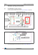
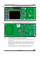
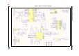
Table Of Contents
- Table 1. Ordering information
- 1 Description
- 2 Features
- 3 Hardware and layout description
- 4 Bill of material
- 5 Federal Communications Commission (FCC) and Industry Canada (IC) compliance statements
- 6 Revision history

DocID026283 Rev 2 9/19
UM1761 Hardware and layout description
18
Please refer to the firmware user manual available on ST web site www.st.com to get more
detail.
3.3 Program/debug the RF transceiver demo board.
In order to flash or debug an STM32 microcontroller application on the EVAL-ST95HF
board, simply connect the 20-pin JTAG/SWD flat ribbon of the STLINK/V2 in-circuit
debugger and programmer to the RF transceiver demonstration board JTAG connector (J3),
then launch STLink.
For more information, documentation about the STLINK/V2 in-circuit debugger and
programmer, please visit www.st.com.
3.4 Electrical schematics
A detailed view of the electrical schemes for the EVAL-ST95HF board can be found in
Figure 6.