
Datasheet


L6219R Functional description
11/16
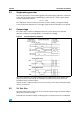
3.4 Single-pulse generator
The pulse generator is a monostable triggered on the positive going edge of the comparator
output. The monostable output is high during the pulse time, toff , which is determined by
the time components R
t
and C
t
.
t
off
= 1.1 · R
t
C
t
The single pulse switches off the power feed to the motor winding, causing the winding
current to decrease during toff. If a new trigger signal should occur during toff, it is ignored.
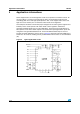
3.5 Output stage
The output stage contains four darlington transistors (source drivers) four saturated
transistors (sink drivers) and eight diodes, connected in two H bridge.
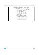
Figure 4. Principle operating sequence
The source transistors are used to switch the power supplied to the motor winding, thus
driving a constant current through the winding. It should be noted however, that is not
permitted to short circuit the outputs.
Internal circuitry is added in order to increase the accuracy of the motor current particularly
with low current levels.
3.6 V
S
, V
SS
, V
Ref
The circuit will stand any order of turn-on or turn-off the supply voltages V
S
and V
SS
. Normal
dV/dt values are then assumed.
Preferably, V
Ref
should be tracking V
SS
during power-on and power-off if V
S
is established.