
Datasheet

Functional description L6219R
10/16
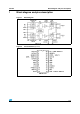
3 Functional description
The circuit is intended to drive both windings of a bipolar stepper motor.
The peak current control is generated through switch mode regulation.There is a choice of
three different current levels with the two logic inputs I
01
- I
11
for winding 1 and I
02
- I
12
for
winding 2.
The current can also be switched off completely
3.1 Input logic (I
0
and I
1
)
The current level in the motor winding is selected with these inputs. (See Figure 4)
If any of the logic inputs is left open, the circuit will treat it has a high level input.
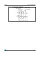
3.2 Phase
This input determines the direction of current flow in the windings, depending on the motor
connections. The signal is fed through a schmidt-trigger for noise immunity, and through a
time delay in order to guarantee that no short-circuit occurs in the output stage during
phase-shift. High level on the phase input causes the motor current flow from out A through
the winding to out B
3.3 Current sensor
This part contains a current sensing resistor (R
S
), a low pass filter (R
C
, C
C
) and three
comparators. Only one comparator is active at a time. It is activated by the input logic
according to the current level chosen with signals I
o
and I
1
. The motor current flows through
the sensing resistor RS. When the current has increased so that the voltage across R
S
becomes higher than the reference voltage on the other comparator input, the comparator
goes high, which triggers the pulse generator.
The max peak current Imax can be defined by:
See figures Figure 3, 4 and 5 for maximum allowable output current and reference voltage
versus V
s
supply.
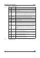
Table 6. Input logic current level
I
0
I
1
Current level
H H No current
L H Low current 1/3 I
O
max
H L Medium current 2/3 I
O
max
L L Maximum current I
O
max
I
max
V
ref
10R
s
------------- -=