
Datasheet


DVIULC6-2x6 Technical information
9/17
Important
An important precaution to take is to put the protection device as close as possible to the
disturbance source (generally the connector).
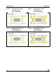
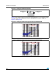
3.3 Crosstalk behavior
Figure 22. Crosstalk phenomena
The crosstalk phenomena is due to the coupling between 2 lines. The coupling factor (β
12
or
β
21
) increases when the gap across lines decreases, particularly in silicon dice. In the
example above the expected signal on load R
L2
is α
2
V
G2
, in fact the real voltage at this point
has got an extra value β
21
V
G1
. This part of the V
G1
signal represents the effect of the
crosstalk phenomenon of the line 1 on the line 2. This phenomenon has to be taken into
account when the drivers impose fast digital data or high frequency analog signals in the
disturbing line. The perturbed line will be more affected if it works with low voltage signal or
high load impedance (few kΩ).
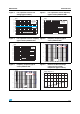
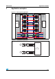
Figure 20. Remaining voltage after the
DVIULC6-2P6 during
positive ESD surge
Figure 21. Remaining voltage after the
DVIULC6-26 during
negative ESD surge
10V/Div
100ns/Div
10V/Div
100ns/Div
Line 1
Line 2
V
G1
V
G2
R
G1
R
G2
DRIVERS
R
L1
R
L2
RECEIVERS
α
β
+
1
12
V
G1
V
G2
α
β
+
2
21
V
G2
V
G1