MC2 Power Systems User's Guide November 2006 Document ID 1110227 Revision 2
Copyright notice Copyright © 2006 Stinger Medical, LLC. All rights are reserved. The software in this product is protected by applicable United States of America copyright laws and international treaty provisions. Publication date November 2006 Printed in U.S.A. Product and version MC2 Power Systems Stinger document control number Document ID 1110227 Revision 2 Reader comments Any comments or suggestions regarding this manual are welcomed and should be emailed to: StingerDocumentation@stingermedical.
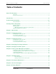
MC2 Power Systems User's Guide Table of Contents Table of Contents About This Document................................................................................................................. v Overview ............................................................................................................................. v Document Conventions.......................................................................................................vi Intended Use ...............................
MC2 Power Systems User's Guide Table of Contents Appendix A: Power System Specifications ............................................................................ 39 Appendix B: Mechanical Specifications ................................................................................. 41 Appendix C: Power System Specifications ............................................................................ 43 Appendix D: System Electromagnetic Emissions and Immunity Declarations ..................
MC2 Power Systems User's Guide About This Document About This Document Overview The MC2 Power System was designed specifically to meet the needs of point-of-care mobile solutions. This document contains all the essential information necessary to use and maintain the MC2 Power System at its maximum potential.
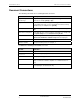
MC2 Power Systems User's Guide About This Document Document Conventions The following conventions are used throughout this document: Convention Description Keyboard keys and function keys Begin with an uppercase letter and appear in bold type, enclosed in brackets; for example, [Enter] or [F1]. Key combinations Are enclosed in brackets and appear in bold type If joined with a plus sign (+), press and hold the first and second key simultaneously; for example, Press [Ctrl+B].
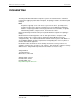
MC2 Power Systems User's Guide Intended Use Intended Use The Stinger Medical workstations and power systems are intended for the continuous non-invasive logging of patient data in hospitals, hospital-type facilities, and intra-hospital transport. Note: Hospital use typically covers such areas as general care floors, operating rooms, special procedure areas, intensive and critical care areas within the hospital-type facilities.
MC2 Power Systems User's Guide Product Safety Information Product Safety Information Safety Guidelines The MC² Power System Series™ is designed to ensure both the highest level of product quality and safety for the user. To maintain both quality and safety, follow the guidelines and instructions in this manual. • Use the power system only as intended. • Do not place the power system near a window. Exposing the power system to rain, water, moisture, or constant, direct sunlight can severely damage it.
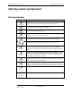
MC2 Power Systems User's Guide Warning Labels and Symbols Warning Labels and Symbols Warning Symbols Symbol Description THIS SYMBOL ALERTS OF AN IMPENDING DANGER. Failure to follow instructions could result in personal injury and/or damage to the unit. USE A NONFLAMMABLE CLEANER WHEN CLEANING THE UNIT! Failure to do so can result in death, explosion, and/or fire. DO NOT LEAVE THE UNIT UNATTENDED AROUND CHILDREN! Failure to do so can result in injury, and/or death. CAUTION: THE POWER SYSTEM IS HEAVY.
MC2 Power Systems User's Guide Warning Labels and Symbols Warning Labels EMI (Electromagnetic Interference) Information Portable and mobile RF communications equipment can affect Medical Electrical Equipment. This equipment should not be used adjacent to or stacked with other equipment. If adjacent or stacked is necessary, this and other equipment should be observed to verify normal operation in the configuration in which it will be used.
MC2 Power Systems User's Guide Warning Labels and Symbols Obtaining Optimum Performance • Plug your MC² Power System into an AC power source (wall outlet) for charging whenever not in use or unattended. • Stinger Medical recommends establishing a protocol for end users requiring the power system be plugged into and AC power source whenever not in use or unattended. • Perform regular preventative maintenance. Failure to do so will void warranty. • Limit current output to 4 amps per channel.
MC2 Power Systems User's Guide Chapter 1: Quick Setup Chapter 1: Quick Setup Note: The quick setup information in this chapter pertains to both the 26 Amp-Hour and 35 Amp-Hour units.
MC2 Power Systems User's Guide Chapter 1: Quick Setup 4 Output voltages are normally pre-configured to power on the intended device(s) prior to shipping. Check the user-selectable switch settings to verify that the correct voltage has been set for each power output channel. 5 Locate the power output plastic cover on the back side of the base. Remove the power output plastic cover and slide the power system unit into base of the cart.
MC2 Power Systems User's Guide Chapter 1: Quick Setup 15 Power ON device(s). If power system unit was sent with a workstation: 1 Check the power system unit and workstation for any physical damage. 2 For the MC2 Power System Series 35 Amp-Hour units, the Power Output Disconnect Switch must be in the ‘ON’ position. 3 Verify that all LED indicators for each power output channel are ON.
MC2 Power Systems User's Guide Chapter 1: Quick Setup 11 Connect the correct power cable to each device. Verify that the correct power cable is being used for the intended device since each power output can be configured to different voltages. 12 Power ON device(s).
MC2 Power Systems User's Guide Chapter 2: 26 Amp-Hour Series Chapter 2: 26 Amp-Hour Series Identifying The Power System Voltage Settings for CPU/Laptop & ACC 1/Monitor Power Outputs (shown left side) ACC 1/ Monitor Power Output Power Management Software Connect (USB Type B) Voltage Settings for ACC 2 & ACC 3 Power Outputs (optional) CPU/Laptop Power Output LED Power Indicator Fuel Gauge Monitor Connect ACC 2 Power Output ACC 3 Power Output 120V 60Hz AC Power Input Cooling Fan Exhaust Fig 6: Identif
MC2 Power Systems User's Guide Chapter 2: 26 Amp-Hour Series Preparing For Operation Parts Listing (Fig 7) • (1) Electronic Enclosure (A) • (1) Battery Enclosure (B) • (1) Cord Set (Fig 10 and 11) 1 Unpack the unit carefully and inspect it for damage. There will be two parts Electronic Enclosure and Battery Enclosure.
MC2 Power Systems User's Guide Chapter 2: 26 Amp-Hour Series Security Screw (C) Fig 9: Security Screw Installation 4 Confirm the green LED power indicators light up beside the outputs. Note: Number of LEDs to light up will vary based upon the number of outputs purchased. 5 Charge your MC² Power System using a Stinger Medical supplied cord set (Fig 10 and 11) for 24 hours prior to use. For more information, see “Charging the Power System”.
MC2 Power Systems User's Guide Chapter 2: 26 Amp-Hour Series Fig 11: Cord Reel 6 Confirm the ‘Charging’ indicator on the fuel gauge is ON. For more information, see “Identifying Fuel Gauge Indicators”. 7 Your Power System is ready for use when the ‘Charged’ indicator is ON.
MC2 Power Systems User's Guide Chapter 2: 26 Amp-Hour Series User-Selectable Switch Settings Voltage Settings Orientation • The diagram below shows each switch location and which output it controls. • The output voltage can be set by user between 12–20V on outputs ‘CPU/Laptop’ and ‘ACC 2 (optional)’ and between 3.3 – 12V on outputs ‘ACC 1/Monitor’ and ‘ACC 3 (optional)’. • All outputs have a maximum continuous current of 4 amps.
MC2 Power Systems User's Guide Chapter 2: 26 Amp-Hour Series 1110227 Revision 2 10 November 2006
MC2 Power Systems User's Guide Chapter 3: 35 Amp-Hour Series Chapter 3: 35 Amp-Hour Series Identifying The Power System Power Output 1 Power Output 2 LED Power Indicator Power Output 3 Power Output 4 Fuel Gauge Monitor Connect Power Management Software Connect (USB Type B) Top view Fig 13: Power Output Port Connectors 1110227 Revision 2 November 2006 11
MC2 Power Systems User's Guide Chapter 3: 35 Amp-Hour Series Right-hand view Power Output Disconnect Switch: Cooling Fan Exhaust ↑ ON ↓ OFF Fig 14: Fan and Power Output Disconnect Switch Rear view 120V 60Hz AC Power Input Fig 15: AC Power Input 1110227 Revision 2 12 November 2006
MC2 Power Systems User's Guide Chapter 3: 35 Amp-Hour Series Preparing For Operation Parts Listing • (1) Power system unit (Fig 16) • (1) Cord Set (Fig 17 and 18) Fig 16: MC2 Power System Series 35 Amp-Hour 1 Unpack components carefully, inspecting for damage. WARNING: Power System is HEAVY! 2 Confirm that the Power Output Disconnect Switch is in the ‘ON’ position. For more information, see “Identifying the Power System.” Verify that the green LED power indicators light up beside the outputs.
MC2 Power Systems User's Guide Chapter 3: 35 Amp-Hour Series 4 Confirm the ‘Charging’ indicator on the fuel gauge is ON (see “Identifying Fuel Gauge Indicators”). 5 Your Power System is ready for use when the ‘Charged’ indicator is ON.
MC2 Power Systems User's Guide Chapter 3: 35 Amp-Hour Series User-Selectable Switch Settings Voltage Settings Orientation • The diagram below illustrates each switch location and which output it controls. • The output voltage can be set by user between 12–20V on Power Output 1 and Power Output 3 and between 3.3 – 12V on Power Output 2 and Power Output 4. • All outputs have a maximum continuous current of 4 amps.
MC2 Power Systems User's Guide Chapter 3: 35 Amp-Hour Series Voltage Settings for Power Output 3 and Power Output 4 (optional) Top view 1110227 Revision 2 16 November 2006
MC2 Power Systems User's Guide Chapter 4: Identifying Fuel Gauge Indicators Chapter 4: Identifying Fuel Gauge Indicators Basic Press & hold 15 seconds to put power system in suspend mode for storage (all LEDs will not be lit). Press momentarily for wake-up (3 seconds). 120V 60Hz AC power connected Internal charger error or battery enclosure not properly connected.
MC2 Power Systems User's Guide Chapter 4: Identifying Fuel Gauge Indicators 1110227 Revision 2 18 November 2006
MC2 Power Systems User's Guide Chapter 5: Charging the Power System Chapter 5: Charging the Power System Note: Where the integrity of the external PROTECTIVE EARTH CONDUCTOR arrangement is in doubt, EQUIPMENT shall be operated from its INTERAL ELECTRICAL POWER SOURCE. Power System Charging In order to charge the power system, plug it in to a 120V 60Hz AC power source using a Stinger Medical supplied cord set.
MC2 Power Systems User's Guide Chapter 5: Charging the Power System Circuit Protection The MC² Power System is thermally protected and self-resetting. For more information, see “No Output Reset Procedure.” The cooling fan maintains a constant ambient temperature inside the electrical enclosure. Deep Discharge Protection Deep discharge of the power system will significantly reduce its cycle life.
MC2 Power Systems User's Guide Chapter 6: Power System Management Software Chapter 6: Power System Management Software Setting Up the Power Management Software • None – no USB cable provided – disregard this section. • Advanced - available at time of purchase only – USB cable included. • System Requirements: Operates ONLY on Windows XP and 2000. Installation Note: If the local computer has any type of anti-spyware or firewall application installed, then you may receive a pop-up notice.
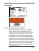
Chapter 6: Power System Management Software MC2 Power Systems User's Guide Installing the Advanced Power Monitor Software Note: The Advanced Power Management Software is available for use with both the 26 AmpHour and 35 Amp-Hour units. The Advanced Monitoring software does not offer the ability to perform an auto-run of the software installation. Manual installation of the software is required to load the application and the USB driver.
MC2 Power Systems User's Guide 4 Chapter 6: Power System Management Software Click the installation button to begin installing the software: The following window is displayed: 5 Accept the default Program Group, and then click Continue. 6 The installation is complete when the following window is displayed: 7 Click OK.
Chapter 6: Power System Management Software MC2 Power Systems User's Guide Configuring Advanced Power Monitor Access Options Creating a desktop icon to start the Advanced Power Monitor application 1 From the Start menu, point to All Programs, and then click Stinger Medical. 2 Right-click Advanced Power Monitor, and then click Copy. 3 Access the Windows desktop. 4 Right-click an empty location on the Windows desktop, and then click Paste.
MC2 Power Systems User's Guide Chapter 6: Power System Management Software Configuring COM Ports The Advanced Power Monitor software does not automatically determine which COM port has been set for the communication between the computer and power system. The user will have to manually determine what COM port has been assigned and manually set it in the Advanced Power Monitor software by performing the following steps: 1 From the Start menu, point to Settings, and then click Control Panel.
Chapter 6: Power System Management Software MC2 Power Systems User's Guide 6 Note the COM port assigned to the USB Serial Port, depicted as follows: 7 Launch the Advanced Power Monitor application. 8 Click Advanced Settings. 9 Click the down arrow in the COM Port field in Advanced Settings: 10 Select the COM port noted in step 6. 11 Click Minimize Settings to close the Advanced Settings options.
MC2 Power Systems User's Guide Chapter 6: Power System Management Software Understanding the Advanced Power Management Software Launch the Advanced Power Monitor application.
MC2 Power Systems User's Guide 1110227 Revision 2 November 2006 28
MC2 Power Systems User's Guide Chapter 7: Troubleshooting Chapter 7: Troubleshooting The following table describes some of the most common troubleshooting options for the MC2 power systems: Symptom Possible Cause Possible Solution No output Re-settable fuse See “No Output Reset Procedure” Power system not charged Charge Power System Power system section not connected Connect both sections of power system together (26 Amp-Hour unit only). See “Preparing for Operation.
Chapter 7: Troubleshooting MC2 Power Systems User's Guide Symptom Possible Cause Possible Solution No LEDs lit on power system Power system not properly connected See “Power Output Disconnect Switch Location” Reconnect power system sections (reference the section of this document specific to your power system) Re-settable fuse See “No Output Reset Procedure” Battery in state of unrecoverable discharge Contact Stinger Medical C.A.R.E.
MC2 Power Systems User's Guide Chapter 7: Troubleshooting 4 Remove the stabilizer plates and separate power system enclosures. 5 Wait 30 seconds. 6 Follow the steps listed in the MC2 Power System Series 26 Amp-Hour topic “Preparing Your MC² Power System for Operation”. 7 Reconnect devices. 8 Plug in to charge until the fully charged notification light has illuminated. If you continue to experience problems with the power system, discontinue use of the system and contact the Stinger Medical C.A.
Chapter 7: Troubleshooting MC2 Power Systems User's Guide 1110227 Revision 2 32 November 2006
MC2 Power Systems User's Guide Chapter 8: Preventative Maintenance Chapter 8: Preventative Maintenance Important note: Please put the MC² Power System on a quarterly preventative maintenance schedule to clean air intake filter(s). Failure to do so will void warranty. Cleaning Procedures When cleaning the MC² Power System, disconnect AC power source and separate electronic enclosure and battery enclosure. Refer to “Charger Timed-out Reset Procedure” for separation instructions.
Chapter 8: Preventative Maintenance 1 Remove the retainer from the finger guard on the power system. 2 Remove the filter media from the retainer. 3 Rinse the filter media thoroughly under cool running water. 4 Carefully squeeze excess water out of the filter media and lay the filter media flat to dry. 5 Once the filter media is dry, replace it into the retainer. 6 Re-install the retainer onto the finger guard.
MC2 Power Systems User's Guide Chapter 9: Service and Support Chapter 9: Service and Support Should your power system or workstation require repair, contact the Stinger Medical C.A.R.E. department to obtain an RMA (Return Merchandise Authorization). An RMA is necessary to return the unit to Stinger Medical for servicing and to maintain the product warranty. Any unit without an RMA will be returned at owner’s expense. See the warranty for more information. Contact the Stinger Medical C.A.R.
Chapter 9: Service and Support MC2 Power Systems User's Guide 1110227 Revision 2 36 November 2006
MC2 Power Systems User's Guide Chapter 10: Battery Disposal Chapter 10: Battery Disposal Industrial batteries contain lead and sulfuric acid, which are both considered ‘hazardous substances’. If batteries are improperly disposed of, for example, thrown in the trash or illegally dumped, these substances can eventually leak out and contaminate the surrounding soil and groundwater supply.
Chapter 10: Battery Disposal 1110227 Revision 2 38 November 2006
MC2 Power Systems User's Guide Appendix A: Power System Specifications Appendix A: Power System Specifications Technical Summary The power system is a self-contained regulated power supply, battery, and charger unit, packed in an aluminum enclosure.
Appendix A: Power System Specifications MC2 Power Systems Battery Manufacturer Powersonic Capacity 26 or 35 Ah each Output Voltage Range 12 V nominal 3.
MC2 Power Systems User's Guide Appendix B: Mechanical Specifications Appendix B: Mechanical Specifications MC2 Power System Series 26 Amp-Hour Maximum Assembled Dimensions: 5.5” x 7.125” x 16.5” Maximum Weight: 30 lbs or less Storage Requirements MC2 Power System Series 35 Amp-Hour Maximum Assembled Dimensions: 5.5” x 7.2” x 16.
Appendix B: Mechanical Specifications 1110227 Revision 2 42 November 2006
MC2 Power Systems User's Guide Appendix C: Power System Specifications Appendix C: Power System Specifications Storage Requirements • The unit must be fully charged prior to storing. • The electronic enclosure on the 26 Amp-Hour unit must be unplugged from AC power source and separated from battery enclosure. • The Power Output Disconnect Switch on the 35 Amp-Hour unit must be set to the OFF position.
Appendix C: Power System Specifications 1110227 Revision 2 44 November 2006
MC2 Power Systems User's Guide Appendix D: System Electromagnetic Emissions and Immunity Declarations Appendix D: System Electromagnetic Emissions and Immunity Declarations MEDICAL ELECTRICAL EQUIPMENT needs special precautions regarding EMC and needs to be installed and put into service according to the EMC information provided in the ACCOMPANYING DOCUMENTS. WARNING: Use of unapproved ACCESSORIES may result in degradation which may result in increased Emissions and decreased Immunity.
Appendix D: System Electromagnetic Emissions and Immunity Declarations MC2 Power Systems User's Guide Table 202 – Guidance and manufacturer’s declaration – electromagnetic immunity – for all EQUIPMENT and SYSTEMS (see 6.8.3.
MC2 Power Systems User's Guide Appendix D: System Electromagnetic Emissions and Immunity Declarations Table 204 – Guidance and manufacturer’s declaration – electromagnetic immunity – for EQUIPMENT and SYSTEMS that are not LIFE-SUPPORTING (see 6.8.3.201 b)) Guidance and manufacturer’s declaration – electromagnetic immunity The MC2 Series is intended for use in the electromagnetic environment specified below. The 2 customer or the user of the MC Series should assure that it is used in such an environment.
Appendix D: System Electromagnetic Emissions and Immunity Declarations b MC2 Power Systems User's Guide Over the frequency range 150 kHz to 80 MHz, field strength should be less than [V1] V/m.
MC2 Power Systems User's Guide Appendix D: System Electromagnetic Emissions and Immunity Declarations Table 206 – Recommended separation distances between portable and mobile RF communications equipment and the EQUIPMENT or SYSTEM – for EQUIPMENT and SYSTEMS that are not LIFE-SUPPORTING (see 6.8.3.
Appendix D: System Electromagnetic Emissions and Immunity Declarations MC2 Power Systems User's Guide 1110227 Revision 2 November 2006 50
MC2 Power Systems User's Guide Glossary Glossary AC – Alternating Current: An electric current that reverses direction in a circuit at regular intervals (found in a standard wall outlet) ACC – Accessory Ambient – Temperature around the circuit board AMPS – Ampere: a unit of electric current Circuit - A closed path followed or capable of being followed by an electric current Com Port – Communications port for data Cord Set – Power cord Cycle – Complete discharge and recharge of power system Cycle Life – Nu
MC2 Power Systems User's Guide Glossary Voltage - The rate at which energy is drawn from a source that produces a flow of electricity in a circuit; expressed in volts 1110227 Revision 2 52 November 2006