STIHL SR 32D, 4DD Instruction Manual Owner's Manual '" iii Assembling Safety Precautions Operating Instructions Maintenance .
&RQWHQWV Controls Safety Precautions Assembly of Unit Fuel Fueling Control Handle Starting Air Filter Adjusting the Carburetor Operating Instructions Checking Spark Plug Replacing the Starter Rope and Rewind Spring Special Accessories Metering Unit Notes on Use of Mistblower 2 4 11 14 15 16 17 19 20 21 22 23 26 27 28 Maintenance Chart 37 Specifications 38 STIHL Incorporated Federal Emission Control Warranty Statement 39 This Manual contains operating and safety instructions for all STIHL SR 320, SR 400
&RQWUROV 1 = Baffle screen 2 = Nozzle 3 = Metering knob 4 = Extension tube 5 = Throttle trigger 6 = Setting lever 7 = Stop switch 8 = Control handle 9 = Stop cock 10 = Pleated hose 11 = Carrying harness 12 = Back plate 13 = Back rest pad 14 = Air filter cover 3 6 7 8 9 5 2 4 11 14 12 10 BA001 KN 1 13 15 = Rubber buffers 16 = Container filler cap 17 = Container 18 = Spark plug boot 19 = Carburator adjustment screws 20 = Choke knob 21 = Fuel filler cap 22 = Starter grip 23 = Muffler 16 17 18 15
'HILQLWLRQV %DIIOH VFUHHQ To vary the direction and shape of the spray. 1R]]OH Directs and widens the spray. 0HWHULQJ NQRE For varying the spraying rate. ([WHQVLRQ WXEH Accessory for lengthening the discharge tube. &DUULQJ KDUQHVV For carrying the unit. )XHO ILOOHU FDS For closing the fuel tank. %DFN SODWH Helps protect the back of the user. 6WDUWHU JULS The grip of the pull starter, which is the device to start the engine.
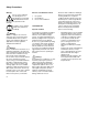
6DIHW\ 3UHFDXWLRQV :DUQLQJ 6DIH XVH RI D PLVWEORZHU LQYROYHV The use of any mistblower may be dangerous. It is important that you read, fully understand and observe the following safety precautions and warnings. Reread the owner‘s manual and the safety instructions periodically. :DUQLQJ Careless or improper use of the machine may cause serious injury. Have your STIHL Dealer show you how to operate your mistblower. Observe all applicable local safety regulations, standards and ordinances.
All the above mentioned precautions do not guarantee that you will not sustain whitefinger disease or carpal tunnel syndrome. Therefore continual and regular users should monitor closely the condition of their hands and fingers. If any of the above symptoms appear, seek medical advice immediately. 3URSHU &ORWKLQJ Clothing must be sturdy and snug-fitting, but allow complete freedom of movement.
Adjust carrying harness to suit your size before starting work. )XHOLQJ This STIHL unit uses an oil-gasoline mixture for fuel (see the chapter on "Fuel" of your owner‘s manual). :DUQLQJ Gasoline is an extremely flammable fuel. If spilled or ignited by a spark or other ignition source, it can cause fire and serious burn injury or property damage. Use extreme caution when handling gasoline or fuel mix. Do not smoke or bring any fire or flame near the fuel.
For specific starting instructions, see the appropriate section of your owner‘s manual. Place the machine on firm ground or other solid surface in an open area. Maintain good balance and secure footing. :DUQLQJ When you pull the starter grip, don‘t wrap the starter rope around your hand. Do not allow the grip to snap back, but guide the starter rope slowly back to permit the rope to rewind properly.
:DUQLQJ Never insert any foreign object into the air intake of the machine or into the nozzle of the mistblower. It wil damage the fan wheel and may cause serious injury to the operator or bystanders as a result of the object or broken parts being thrown out at high speed. Do not place the mistblower on the ground when operating at high speed, because small objects such as sand, gras, dust, etc. may be pulled into the air intake and damage the fan wheel.
)LOOLQJ WKH &RQWDLQHU To reduce the risk of contaminating the surrounding environment, be careful not to overfill the container with chemical solution. If you fill the container with a hose attached to a water pipe be sure the end of the hose is out of the solution to reduce the risk of chemicals being sucked into the water pipe in the case of a sudden vacuum. Calculate the correct amount of chemical solution so that it is used up at one time.
:DUQLQJ In order to reduce the risk of fire, do not modify or remove any part of the muffler or spark arrestor. Tighten all nuts, bolts and screws except the carburetor adjustment screws after each use. Keep spark plug and wire connection tight and clean. The spark plug electrode gap should be checked with a feeler gauge at least every 50 operating hours and reset if necessary. Fit a new spark plug if the electrodes are badly pitted.
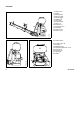
Assembly of Unit Top: Ellbow fitted to fan housing Center: Spraying attachment fitted Bottom: Stop cock lever in vertical position The unit is partly disassembled for ease of shipment and must be completely assembled before it is used for the first time. The tools on the underside of the unit (1 combination wrench and 1 carburetor screwdriver) should be used for the assembly work. Mounting the elbow - Line up the stops on the elbow (1) and fan housing stub (2).
- Rotate the control handle (10) to the left (counterclockwise) until it is horizontal. - Rotate the extension tube 12 to the left (counterclockwise) until the metering unit (13) points in the same direction as the control handle. - Tighten the clamp screw (11). (Observe instructions in chapter "Adjusting the control handle") - Push the free end of the liquid hose (14) over the stub on the stop cock (15) and secure in position with the hose clip (16).
Top: Range of rotation of tube Center: Range of adjustment of control handle Bottom: Pulling ends of straps downward (left) Lifting tabs of strap adjusters (right) The pivot-mounted pleated hose allows the blower tube or spraying attachment to be rotated about 90° to the left or right (i.e. counterclockwise or clockwise) from the center position (control handle vertical). Adjusting the control handle You can adjust the position of the control handle on the pleated hose to suit your reach.
)XHO This engine is certified to operate on unleaded gasoline and with the mix ratio 50:1. We recommend STIHL 50:1 two-stroke engine oil since it is specially formulated for use in STIHL engines. Your two-stroke engine requires a mixture of brand-name gasoline and quality two-stroke engine oil with the classification TC. Do not use BIA or TCW (two-stroke water cooled) mix oils! Use regular branded unleaded gasoline with a minimum octane rating of 90 RON (U.S.A./Canada: pump octane min. 89!).
Before fueling, clean the filler cap and the area around it to ensure that no dirt falls into the tank. Always thoroughly shake the mixture in the canister before fueling your machine. 353BA009 353BA008 )XHOLQJ Change the fuel pick up body every year. Before storing your machine for a long period, drain and clean the fuel tank and run engine until carburetor is dry.
Control Handle Top: Control handle with stop switch, throttle trigger and setting lever Center: Setting lever in lower end position Bottom: Stop cock lever The control handle has two functions. It is used to aim the airstream or the spray in the required direction. The controls (stop switch, throttle trigger and setting lever) are used to select the required engine operating condition. The stop switch (1) shuts down the engine. The engine is ready to start when the stop switch is in the "I" position.
Starting Top: Throttle trigger and setting lever in "start" position Center: Rotary choke knob in "cold start" position Bottom: Rotary choke knob in "warm start" position Before starting, place the unit on a clear patch of ground. Make sure you have a firm foothold, keep a firm grip on the machine and check that there are no objects which could be sucked in by the fan (between engine and backplate). 1. Starting procedure 1.1 Slide the stop switch (1) to "I".
Top: Starting Center: Setting lever in Lower end position Bottom: Stop switch on "STOP" 2. To start, hold the top of the machine with your left hand and put one foot on the base plate to prevent it slipping. Pull the starter grip slowly with your right hand until you feel it engage and then give it a brisk strong pull. Do not pull the starter rope out more than about 70 cm (27") as it might otherwise break. Do no allow the starter rope to snap back.
Air Filter Component parts in correct sequence Erratic idling behavior; poor acceleration Idle setting too lean; turn low speed adjusting screw (2) counterclockwise until engine runs and accelerates smoothly. Exhaust smokes at idle speed Idle speed setting too rich; turn low speed adjusting screw (2) clockwise until engine speed drops. Then turn screw back one quarter turn and check that engine still accelerates smoothly when you open the throttle.
$GMXVWLQJ WKH &DUEXUHWRU L 0RWRUPDQDJHPHQW Exaust emissions are controlled by the design of the fundamental engine parameters and components (e.g. carburation, ignition, timing and valve or part timing) without the addition of any major hardware. The carburetor comes with a standard setting. This is the optimum setting to ensure your machine will operate reliably with the lowest possible emission under most operating conditions.
2SHUDWLQJ ,QVWUXFWLRQV 6WRULQJ WKH 0DFKLQH 'XULQJ EUHDN LQ SHULRG For periods of about 3 months or longer: A factory new machine should not be run at high revs (full throttle off load) for the first three tank fillings. This avoids unnecessary high loads during the break-in period. As all moving parts have to bed in during the break-in period, the frictional resistances in the engine are greater during this period. The engine develops its maximum power after about 5 to 15 tank fillings.
A • 000BA039 KN &KHFNLQJ 6SDUN 3OXJ Use only resistor type spark plugs of the approved range. 1 • Fit a new spark plug after approx. 100 operating hours or earlier if the electrodes are badly eroded. :DUQLQJ To reduce the risk of fire and burn injury, use only spark plugs authorized by STIHL (see “Specifications”). Always press spark plug boot snugly onto spark plug terminal of the proper size. (Note: If terminal has detachable SAE adapter nut, it must be attached.
5HSODFLQJ 6WDUWHU 5RSH DQG 5HZLQG 6SULQJ 6 1 1 2 7 • • Remove the three screws . Lift the starter cover off the engine. 353BA041 KN 353BA027 1 • • Remove the spring clip . Remove the rope rotor with washer and pawl . • • • • Ease the cap out of the starter grip. Remove remaining rope from the rotor and grip. Tie a simple overhand knot in the end of the new starter rope 1113 195 8200 - and then thread the rope through the top of the grip and the rope bush .
5HSODFLQJ D EURNHQ UHZLQG VSULQJ 353BA036 T • • • • Thread the rope through the rotor and secure it with a simple overhand knot. • • • • • Coat rope rotor bearing bore with non-resinous oil.
• • • • Fit new spring housing - bottom plate must face downward. Engage outer spring loop over the lug. Refit the rope rotor. Go to "Tensioning rewind spring". If the spring has popped out and uncoiled: Refit it in the counterclockwise direction - start outside and work inward. 353BA030 353BA029 • • • When starter rope is fully extended it must be possible to rotate the rotor at least another half turn.
Special accessories Lap belt The lap belt is standard on some models and can be retrofitted to all mistblowers. It ensures that the backplate is always positioned snugly against the user's back. Back padding Additional back padding is available to further enhance wear comfort. It is attached to the backplate next to the standard padding.
Metering Unit Nozzle with metering unit The flow rate can be infinitely varied by means of the metering knob (1) on the nozzle (2). Metering knob position "1" is the minimum flow rate and "6" the maximum. The required number on the metering knob (1) must be lined up with the molded lug (3). The numbers on the metering knob (1) represent the following spray rates: Checking the metering unit (without booster pump) 1.
Notes on Use of Mistblowers Comparison of principles of backack mistblowers and backpack high-pressure sprayers The methods of operation of low-volume mistblowers and high-pressure sprayers are fundamentally different. In the case of the high-pressure sprayer the carrier liquid in the solution serves as the transport medium for the active ingredient. The solution is applied at a comparatively high pressure produced by a high-pressure pump and a small-bore nozzle.
• • • Long horizontal and vertical spraying range. Working time is saved not only during the actual application, but also during the preparations, i.e. less spray solution has to be transported to the site and fewer refilling stops are required. The formation of very fine droplets enables the concentration of active ingredient to be increased and the total amount of spray solution to be reduced - a water saving of up to 80%.
In this case 0.6 litres pesticide would have to be mixed with 600 litres water to make up the spray solution. However, in low-volume mistblowing only one quarter of the water quantity is required for the same amount of pesticide. This means that the concentration used is four times higher than for high-pressure spraying. The 0.6 litres pesticide therefore have to be mixed with only 150 litres water. That is the quantity of solution required for mistblowing 1 hectare.
Preparations for mistblowing Before starting work it is necessary to determine the following points, which affect the liquid discharge rate per unit area and thus the distribution of active ingredient in the crop: • • • • Working width Walking speed Unit's discharge rate per unit time Position of spray tube (angle from horizontal) Among other factors, the working width is dependent on the crop and is determined by the distance between rows of trees, shrubs and bushes.
Important: All values must be inserted in the equation in the units specified. Note that hectares have to be multiplied by 10,000 to obtain square meters. Assuming a working width of 3 m and a walking speed of 60 m/min, the calculation of the above example would be as follows: 54 I • 60 m • 3 m 1 min • 3,600 m 2 = 2.7 I/min The metering unit on the mistblower would therefore have to be set to 2.7 I/min. It this rate is not marked directly on the scale, select an intermediate setting.
33
Use of mistblower In mistblowing the solution flows from the container, down through the open shut-off cock and the metering nozzle to the spray tube. The jet of solution is injected into the airstream, atomized and discharged. The airstream is permeated more or less uniformly with very fine droplets. The factors which influence the liquid discharge rate per unit area are either fixed by the setting (discharge rate per unit time) or determined by the operator. Walking speed and working width can vary.
Top: Center: Bottom: Tapered baffle screen Deflector baffle screen Dual defector baffle screen In our example the setting of the metering unit would have to be reduced by 17%, from 2.7 to 2.24 I/min. If this is not done, the quantity of solution required would increase 17%, from 54 liters to 63.2 liters. If both these variations occurred at the same time, the setting of the metering unit would have to be reduced by 27%, from 2.7 to 1.
Detachable nozzle and baffle screens (accessory) Some important conversion factors It may be necessary to change the pattern and direction of the spray jet for certain crops and applications. A detachable nozzle and various baffle screens are available for this purpose. 1m 1m 1 yd 1 yd 1 ft 1 m/s 1 ft/s = = = = = = = 1,094 39,370 0,914 3 12 3,28 0,305 yd in m ft in ft/s m/s 1 ha 1 acre 1 ar 1 acre 1l 1I 1I = = = = = = = 2,470 0,405 0,025 4840 0,264 2,11 33,81 acre ha acre yd US gal US pt fl.
Complete machine Control handle Air filter Filter in fuel tank Fuel tank Carburetor Spark plug Cylinder fins Spark arresting screen All accessible screws and nuts (not adjusting screws) Container with line Metering unit Rubber vibration buffers The user of this unit should carry out only the maintenance operations described in this manual. Other repair work may be performed only by an authorized STIHL Service dealer.
Specifications Engine STIHL single cylinder two-stroke engine SR 320 Displacement: 44.9 cm³ (2.74 cu.in) Bore: 41 mm (1.61 in) Stroke: 34 mm (1.34 in) Engine power: 2,0 kW For US only: 320 L Bystander noise per ANSI B 175.2 -1990 70 dB (A) SR 400 56.5 cm³ (3.45 cu.in) 46 mm (1.81 in) 34 mm (1.34 in) 2,5 kW Ignition System Type: Electronic magneto ignition (breakerless) Spark plug (suppressed): NGK BPMR 7 A or Bosch WSR 6 F Heat range 200 Electrode gap 0.5 mm (0.02 in) Spark plug thread: M 14x1.25; 9.
67,+/ ,QFRUSRUDWHG )HGHUDO (PLVVLRQ &RQWURO :DUUDQW\ 6WDWHPHQW
purchaser that your engine is free from defects in materials and workmanship which cause the engine to fail to conform with applicable regulations for a period of two years. Mechanical diagnostic work will be performed at an authorized STIHL servicing dealer. Emission test may be performed either at STIHL Incorporated or at any independent test laboratory.
- &. WARNING! The engine exhaust from this product contains chemicals known to the State of California to cause cancer, birth defects or other reproductive harm.