
User Instructions

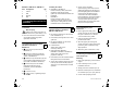
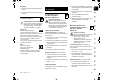

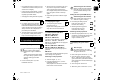
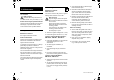
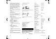
Table Of Contents
- 1. Table of contents
- 2. Notes on the instruction manual
- 3. Machine overview
- 4. For your safety
- 5. Description of symbols
- 6. Standard equipment
- 7. Preparing the machine for operation
- 8. Controls
- 9. Safety devices
- 10. Notes on working with the machine
- 11. Operating the machine
- 12. Maintenance
- 13. Transport
- 14. Environmental protection
- 15. Minimising wear and preventing damage
- 16. Standard spare parts
- 17. EU - Declaration of conformity
- 18. Technical specifications
- 19. Troubleshooting
- 20. Service schedule
- 1. Obsah
- 2. O tomto návode na obsluhu
- 3. Popis stroja
- 4. Pre vašu bezpečnosť
- 5. Popis symbolov
- 6. Rozsah dodávky
- 7. Príprava stroja na prevádzku
- 8. Ovládacie prvky
- 9. Bezpečnostné zariadenia
- 10. Pokyny pre prácu
- 11. Uvedenie stroja do prevádzky
- 12. Údržba
- 13. Preprava stroja
- 14. Ochrana životného prostredia
- 15. Opatrenia na minimalizovanie opotrebovania a na zabránenie vzniku škôd
- 16. Bežné náhradné diely
- 17. Prehlásenie o zhode výrobcom - EÚ
- 18. Technické údaje
- 19. Hľadanie porúch
- 20. Servisný plán
- 1. İçindekiler
- 2. Kullanım kılavuzu hakkında
- 3. Cihazın tarifi
- 4. Güvenliğiniz için
- 5. Sembol açıklamaları
- 6. Teslimat kapsamı
- 7. Cihazın çalışmaya hazır hale getirilmesi
- 8. Kullanma elemanları
- 9. Güvenlik tesisatları
- 10. Çalışmaya yönelik uyarılar
- 11. Cihazın çalıştırılması
- 12. Bakım
- 13. Nakliye
- 14. Çevre koruma
- 15. Aşınmanın en aza indirgenmesi ve hasar oluşumunun önlenmesi
- 16. Sık kullanılan yedek parçalar
- 17. EU Uygunluk Beyanı
- 18. Teknik veriler
- 19. Hata arama
- 20. Servis planı
- 1. Tartalomjegyzék
- 2. A használati útmutatóhoz
- 3. A gép leírása
- 4. A biztonság érdekében
- 5. A szimbólumok leírása
- 6. Szállítási terjedelem
- 7. A gép összeszerelése
- 8. Kezelőelemek
- 9. Biztonsági berendezések
- 10. Munkavégzési tanácsok
- 11. A gép üzembe helyezése
- 12. Karbantartás
- 13. Szállítás
- 14. Környezetvédelem
- 15. A kopás minimalizálása és a meghibásodások elkerülése
- 16. Általános pótalkatrészek
- 17. A gyártó uniós megfelelőségi nyilatkozata
- 18. Műszaki adatok
- 19. Hibakeresés
- 20. Szervizelési időpontok
- 1. Sadržaj
- 2. O ovom uputstvu za upotrebu
- 3. Opis uređaja
- 4. Za vašu bezbednost
- 5. Opis simbola
- 6. Sadržaj paketa
- 7. Pripremanje uređaja za rad
- 8. Elementi za rukovanje
- 9. Bezbednosni uređaji
- 10. Uputstva za rad
- 11. Puštanje uređaja u rad
- 12. Održavanje
- 13. Transport
- 14. Zaštita životne sredine
- 15. Smanjivanje istrošenosti i izbegavanje oštećenja
- 16. Uobičajeni rezervni delovi
- 17. EC Izjava proizvođača o usaglašenosti
- 18. Tehnički podaci
- 19. Traženje grešaka
- 20. Plan servisiranja
- 1. Sadržaj
- 2. O ovim uputama za uporabu
- 3. Opis uređaja
- 4. Za vašu sigurnost
- 5. Opis simbola
- 6. Opseg isporuke
- 7. Priprema uređaja za rad
- 8. Upravljački elementi
- 9. Sigurnosne naprave
- 10. Napomene uz rad
- 11. Pokretanje uređaja
- 12. Održavanje
- 13. Transport
- 14. Zaštita okoliša
- 15. Minimaliziranje trošenja i izbjegavanje šteta
- 16. Uobičajeni rezervni dijelovi
- 17. EU izjava o usklađenosti
- 18. Tehnički podaci
- 19. Traženje pogrešaka
- 20. Servisni plan
- 1. Obsah
- 2. O tomto návodu k použití
- 3. Popis stroje
- 4. Pro vaši bezpečnost
- 5. Popis symbolů
- 6. Rozsah dodávky
- 7. Příprava stroje k provozu
- 8. Ovládací prvky
- 9. Bezpečnostní zařízení
- 10. Pokyny pro práci
- 11. Uvedení stroje do provozu
- 12. Údržba
- 13. Přeprava stroje
- 14. Ochrana životního prostředí
- 15. Opatření pro minimalizování opotřebení a zabránění vzniku škod
- 16. Běžné náhradní díly
- 17. Prohlášení o shodnosti výroby EU
- 18. Technické údaje
- 19. Hledání závad
- 20. Servisní plán
- 1. Satura rādītājs
- 2. Par šo lietošanas pamācību
- 3. Ierīces apraksts
- 4. Jūsu drošībai
- 5. Simbolu apraksts
- 6. Piegādes komplekts
- 7. Ierīces sagatavošana darbam
- 8. Vadības elementi
- 9. Drošības ierīces
- 10. Norādījumi par darbu
- 11. Ierīces sagatavošana darbam
- 12. Apkope
- 13. Transportēšana
- 14. Vides aizsardzība
- 15. Nodiluma samazināšana un bojājumu novēršana
- 16. Parastās rezerves daļas
- 17. ES atbilstības deklarācija
- 18. Tehniskie parametri
- 19. Darbības traucējummeklēšana
- 20. Apkopes grafiks
- 1. Turinys
- 2. Apie šią naudojimo instrukciją
- 3. Įrenginio aprašymas
- 4. Jūsų saugumui
- 5. Simbolių aprašymas
- 6. Komplektas
- 7. Įrenginio paruošimas eksploatacijai
- 7.1 Bendroji informacija
- 7.2 Vienoje pusėje tvirtinamos valdymo rankenos montavimas (RM 448 PC, RM 448 TC, RM 448 VC)
- 7.3 Abiejose pusėse tvirtinamos valdymo rankenos montavimas (RM 443, RM 443 T, RM 448 PT, RM 448 T, RM 448 TX)
- 7.4 Žolės surinkimo dėžės rinkimas
- 7.5 Starterio troso užkabinimas ir nukabinimas
- 7.6 Degalai ir variklio alyva
- 8. Valdymo elementai
- 9. Saugos įtaisai
- 10. Darbo nuorodos
- 11. Įrenginio naudojimo pradžia
- 12. Techninė priežiūra
- 13. Gabenimas
- 14. Aplinkos apsauga
- 15. Dėvėjimosi mažinimas ir priemonės, padedančios išvengti gedimų
- 16. Įprastos atsarginės dalys
- 17. ES gamintojo atitikties deklaracija
- 18. Techniniai duomenys
- 19. Gedimų paieška
- 20. Techninės priežiūros planas
- 1. Cuprins
- 2. Despre aceste instrucţiuni de utilizare
- 3. Descrierea aparatului
- 4. Pentru siguranţa dvs.
- 5. Descrierea simbolurilor
- 6. Conţinutul pachetului
- 7. Pregătirea aparatului pentru lucru
- 8. Elemente de comandă
- 9. Dispozitive de siguranţă
- 10. Indicaţii pentru lucru
- 11. Punerea în funcţiune a aparatului
- 12. Întreţinerea
- 13. Transportul
- 14. Protecţia mediului
- 15. Reducerea uzurii şi evitarea deteriorărilor
- 16. Piese de schimb cerute mai frecvent
- 17. Declaraţia de conformitate UE
- 18. Specificaţii tehnice
- 19. Identificarea cauzelor defecţiunilor
- 20. Planul de întreţinere
- 1. Περιεχόμενα
- 2. Σχετικά με αυτές τις οδηγίες χρήσης
- 3. Περιγραφή εργαλείου
- 4. Για τη δική σας ασφάλεια
- 5. Περιγραφή συμβόλων
- 6. Περιεχόμενα συσκευασίας
- 7. Προετοιμασία του εργαλείου για χρήση
- 8. Χειριστήρια
- 9. Συστήματα ασφαλείας
- 10. Υποδείξεις για την εργασία
- 11. Θέση του εργαλείου σε λειτουργία
- 12. Συντήρηση
- 13. Μεταφορά
- 14. Προστασία περιβάλλοντος
- 15. Ελαχιστοποίηση φθορών και αποφυγή βλαβών
- 16. Συνηθισμένα ανταλλακτικά
- 17. Πιστοποιητικό συμβατότητας ΕΕ
- 18. Τεχνικά στοιχεία
- 19. Εντοπισμός βλαβών
- 20. Πρόγραμμα συντήρησης
- 1. Съдържание
- 2. За тази инструкция за експлоатация
- 3. Описание на уреда
- 4. За Вашата безопасност
- 5. Описание на символите
- 6. Окомплектовка
- 7. Подготовка на уреда за пускане в експлоатация
- 8. Командни елементи
- 9. Защитни приспособления
- 10. Указания за работа
- 11. Пускане на уреда в експлоатация
- 12. Поддръжка
- 13. Транспортиране
- 14. Опазване на околната среда
- 15. Минимизиране на износването и предотвратяване на повреди
- 16. Обичайни резервни части
- 17. ЕС Декларация за съответствие
- 18. Технически данни
- 19. Откриване на повреди
- 20. Сервизен план
- 1. Sisukord
- 2. Selles kasutusjuhendis
- 3. Seadme kirjeldus
- 4. Ohutusnõuded
- 5. Sümbolite kirjeldus
- 6. Tarnekomplekt
- 7. Seadme töökorda seadmine
- 8. Juhtelemendid
- 9. Turvaseadised
- 10. Juhised töötamiseks
- 11. Seadme käivitamine
- 12. Hooldus
- 13. Transport
- 14. Keskkonnakaitse
- 15. Kulumise minimeerimine ja kahjude vältimine
- 16. Tavalised varuosad
- 17. EL-i vastavusdeklaratsioon
- 18. Tehnilised andmed
- 19. Tõrkeotsing
- 20. Teenindusplaan
- 1. Mündəricat
- 2. Bu istifadə üzrə təlimata dair
- 3. Cihazın təsviri
- 4. Sizin təhlükəsizliyiniz üçün
- 5. İşarələrin təsviri
- 6. Çatdırılma həcmi
- 7. Cihazı işə hazırlamaq
- 8. Xidmət elementi
- 9. Təhlükəsizlik qurğusu
- 10. İşə dair göstərişlər
- 11. Cihazı işə salmaq
- 12. Texniki baxış
- 13. Nəql
- 14. Ətraf mühitin qorunması
- 15. Tullantını azaltmaq və zərərlərin qarşısını almaq
- 16. Qalıq ehtiyat hissələri
- 17. Aİ – Uyğunluğun təsdiqlənməsi
- 18. Texniki məlumatlar
- 19. Xətanın axtarılması
- 20. Xidmət planı
- 1. Мазмұны
- 2. Аталмыш пайдалану жөніндегі нұсқаулық жайында
- 3. Құрылғылардың сипаты
- 4. Қауіпсіздік шаралары
- 5. Таңбалардың сипаттамасы
- 6. Жеткізілім жиынтығы
- 7. Қолданысқа дайындау
- 8. Басқару элементтері
- 9. Сақтандырғыш құрылғылар
- 10. Жұмыс нұсқаулары
- 11. Қолданысқа енгізу
- 12. Техникалық қызмет көрсету
- 13. Тасымалдау
- 14. Қоршаған ортаны қорғау
- 15. Тозу дәрежесін барынша азайту және зақымдардан қорғау
- 16. Басқа да қосалқы бөлшектер
- 17. ЕО талаптарына сәйкестік туралы декларация
- 18. Техникалық деректер
- 19. Ақаулықтарды іздеу
- 20. Техникалық қызмет көрсету жоспары

0478 111 9841 B - EN
20
RM 448 PC, RM 448 TC, RM 448 VC:
7.1 General
● Place the machine on level and firm
ground when performing all the
operations described.
7.2 Installing the mono handlebar
(RM 448 PC, RM 448 TC,
RM 448 VC)
● 1 Insert sleeve (I) in the bore on
handlebar (1).
● 2 Fit the two washers (K) with the
convex side facing inwards onto the
sleeve in handlebar (1).
● 3 Hold sleeve (I) and washers (K) and
insert together with handlebar (1) into
the holder on handlebar bracket (2).
● 4 Insert bolt (J) from the outside
inwards through the bores in
handlebar (1) and in handlebar
bracket (2).
● 5 Screw on nut (L).
● 6 Tighten bolt (J). Tightening torque:
18 - 22 Nm
Installing the cables:
● RM 448 PC, RM 448 TC:
Route motorstop cable (3) and self-
propulsion cable (4) into cable
guides (6) of the handlebar bracket and
handlebar.
RM 448 VC:
Route motorstop cable (3), self-
propulsion cable (4) and Vario drive
cable (5) into cable guides (6) of the
handlebar bracket and handlebar.
7.3 Installing the dual handlebar
(RM 443, RM 443 T, RM 448 PT,
RM 448 T, RM 448 TX)
● Fit protective sleeves (H) onto the two
lower handlebars (1).
● Insert bolt (F) through the bore in cable
guide (G).
● Fit upper handlebar (2) onto lower
handlebar sections (1).
● Left-hand side:
Attach cable guide (G) to
motorstop cable (3).
● Right-hand side (RM 443 T,
RM 448 PT, RM 448 T, RM 448 TX):
Attach cable guide (G) to self-
propulsion cable (4).
● Insert bolt (F) from the outside inwards
through the bores on both sides.
● Screw quick clamping devices (E) onto
bolts (F) (the screw should project by
about one screw thread turn) and fold
upwards.
● Check correct assembly:
Quick-clamping devices (E) must be
sufficiently tightened so that they are
pressed tightly against the handlebar
and the upper handlebar is firmly
connected to the lower handlebar.
If the handlebar is not firmly installed or
the quick-clamping devices are not
correctly located, open the quick-
clamping devices and turn them until
they are securely fastened.
7.4 Assembling the grass
catcher box
● Fit the upper part of the grass
catcher box (B) onto the lower part of
the grass catcher box (C). Ensure
correct location in the guides.
● Push pin (D) through the bores
provided from inside.
● Allow the upper part of the grass
catcher box (B) to engage in the lower
part of the grass catcher box using
slight pressure.
● Attach the grass catcher box (Ö 8.3).
7.5 Attaching and detaching the
recoil starter rope
Attaching
● Detach the spark plug socket from the
engine.
● Press motorstop lever (1) to the
handlebar and hold.
● Slowly pull out recoil starter rope (2).
● Release motorstop lever (1) and attach
recoil starter rope (2) to rope guide (3).
● Connect the spark plug socket.
Item Designation Qty.
I Sleeve 1
J Bolt 1
K Washer 2
L Nut 1
7. Preparing the machine for
operation
Risk of injury!
Observe the safety instructions in
the section "For your safety" (Ö 4.).
3
4
5
6