
Operators Manual


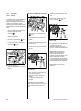

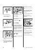


Table Of Contents
- Contents
- 1. Introduction
- 2. Safety Precautions
- 3. Specifications
- 4. Troubleshooting
- 5. Cutting Attachment
- 6. Clutch
- 7. Chain Brake
- 8. Engine
- 9. Ignition System
- 10. Rewind Starter
- 11. Servicing the AV System
- 12. Master Control Lever
- 13. Chain Lubrication
- 14. Fuel System
- 15. Special Servicing Tools
- 16. Servicing Aids

93MS 171, MS 181, MS 211
14.8.2 Removing and Installing
– Remove the handle frame,
b 11.4
: Pry out the tank vent (1) as
shown (arrow).
Always install a new tank vent.
– Disconnect the fuel hose (1),
check and replace if necessary.
: Push the new tank vent (2) into
the fuel hose (1) as far as stop.
533RA403 TG
1
533RA404 TG
21
– Coat seat of tank vent with STIHL
Press Fluid, b 16
: Press the tank vent into its seat
(arrows) in the handle frame (1)
by hand.
– Install the handle frame, b 11.4
: Push the fuel hose (1) onto the
stub (arrow).
– Reassemble all other parts in the
reverse sequence.
– Tightening torques, b 3.5
14.8.3 Manual Fuel Pump
Not installed in all machine
versions. A faulty manual fuel pump
must be replaced.
533RA405 TG
1
533RA406 TG
1
– Remove the filter base, b 14.2
– Remove the carburetor, b 14.3
: Pull the fuel hose (1) out of the
guides (arrows).
: Check the fuel hose (1), pull it off
the connector (2) and replace if
necessary.
– Install in the reverse sequence.
: Press the retaining tabs (arrows)
together and pull out the fuel
pump (1).
– Pull the fuel pump (1) off the fuel
hose (2).
1
2
533RA407 TG
1
533RA408 TG
2