
Operators Manual


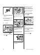
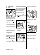

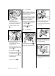
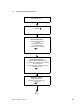
Table Of Contents
- Contents
- 1. Introduction
- 2. Safety Precautions
- 3. Specifications
- 4. Troubleshooting
- 5. Cutting Attachment
- 6. Clutch
- 7. Chain Brake
- 8. Engine
- 9. Ignition System
- 10. Rewind Starter
- 11. Servicing the AV System
- 12. Master Control Lever
- 13. Chain Lubrication
- 14. Fuel System
- 15. Special Servicing Tools
- 16. Servicing Aids

48 MS 171, MS 181, MS 211
– Install the switch shaft, b 12.1
: Push ground wire connector with
protective tube (2) onto the
contact spring (1).
: Position the ground wire (1)
against the protective rib (arrow)
– to avoid unintentional
disconnection
533RA169 TG
1
2
533RA173 TG
1
: Check operation
– the short circuit wire’s
connector must touch the contact
spring (arrow) in position “
0“.
– The ground and short circuit
wires must be laid close to the
housing and properly seated in
the guides, b 9.6.2
– Reassemble all other parts in the
reverse sequence.
– Tightening torques, b 3.5
533RA174 TG