
Operators Manual


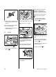
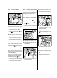

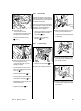
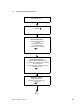
Table Of Contents
- Contents
- 1. Introduction
- 2. Safety Precautions
- 3. Specifications
- 4. Troubleshooting
- 5. Cutting Attachment
- 6. Clutch
- 7. Chain Brake
- 8. Engine
- 9. Ignition System
- 10. Rewind Starter
- 11. Servicing the AV System
- 12. Master Control Lever
- 13. Chain Lubrication
- 14. Fuel System
- 15. Special Servicing Tools
- 16. Servicing Aids

41MS 171, MS 181, MS 211
The ignition module (1) and ignition
lead (2) are an assembly.
– Check the ignition module (1) and
ignition lead and replace the
ignition module if necessary.
: Remove the insulator (1) and pull
off the retainer (2).
– Check the retainer and insulator
and replace if necessary.
– Check the spark plug boot and
replace if necessary, b 9.4
– Troubleshooting, b 4.5
: Fit the retainer (1).
533RA143 TG
1
2
533RA144 TG
1
2
533RA145 TG
1
– Fit the insulator (1) so that the
stop (2) is against the upper hole.
: Secure the insulator (1) with the
lugs (arrows) on the bosses.
: Position the ignition module (1)
so that the ignition lead (2) is on
the left and insert the screw
(arrow) with washer
– do not tighten down yet.
: Fit the wire terminal (1) so that it
is against the stop (arrow) and
insert the screw – do not tighten
down yet.
533RA146 TG
1
2
533RA147 TG
1
2
533RA148 TG
1
: Fit the ground wire (2) in the
retainer (1) – ground wire must
face the cylinder (arrow).
– Push the ignition module (1) back
– the flywheel must turn freely.
: Rotate the flywheel until the
magnet poles (arrows) are next to
the ignition module.
533RA118 TG
1
2
N
S
533RA149 TG
1