
Operation Manual
KM 111 R, KM 131, KM 131 R
English
9
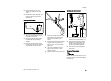
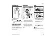
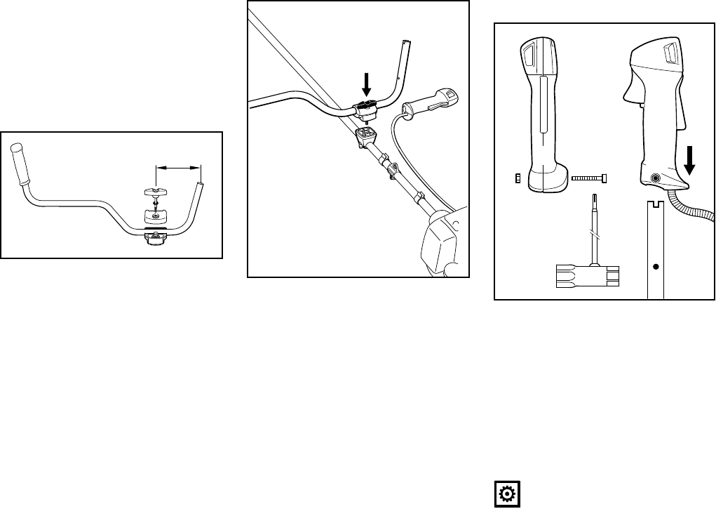
N Pull out the wing screw – the
washer (6) remains on the wing
screw.
N Separate the clamp moldings – the
springs (4 and 5) remain in the
lower clamp.
Securing the handlebar
N Place the handlebar (7) in the lower
clamp (1) so that distance A is no
more than 15 cm (6 in).
N Place the upper clamp in position
and hold both clamp moldings
together.
N Push the wing screw through the
two clamps as far as stop – hold all
parts together and secure them.
N Place the secured assembly on the
handle support (8) with the wing
screw at the side nearest the
engine.
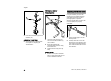
N Push the wing screw into the handle
support as far as stop and then
screw it down – but do not finally
tighten yet.
N Line up the handlebar at a right
angle to the drive tube – check
distance A again.
N Tighten down the wing screw firmly.
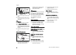
Mounting the control handle
N Take out the screw (9) – the nut (10)
remains in the control handle (11).
N Push the control handle onto the
handlebar (7) until the holes (13)
line up – the throttle trigger (12)
must point towards the gearbox.
N Insert the screw (9) and tighten it
down firmly.
Fitting the Throttle Cable
NOTICE
Do not kink the throttle cable or lay it in
tight radii – make sure the throttle trigger
moves freely.
1
7
A
250BA046 KN
0000-GXX-0510-A0
8
13
9
11
12
7
13
0000-GXX-0511-A0
10