
Operation Manual

KM 111 R, KM 131, KM 131 R
English
8
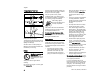
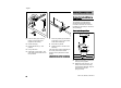
N Insert the clamp (3) in the loop
handle (4) and position them
together on the shaft (5)
N Position clamp (6)
N Position barrier bar (2) – note
position!
N Line up the holes
N Insert bolts (7) in the holes – and
screw them into the barrier bar as
far as possible
N Fit the loop handle (4) at a distance
of (A) approx. 20 cm (8 in) forward
of the control handle (8)
N Orient the loop handle
N Tighten the bolts – lock the nuts if
necessary
The sleeve (9) is present depending on
the country and must be located
between the loop handle and control
handle.
Always leave the barrier bar attached.
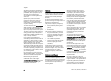
Mounting Bike Handle with Swiveling
Handle Support
The machine is supplied with the
swiveling handle support already
mounted on the shaft. To mount the
handlebar it is necessary to remove the
clamp moldings.
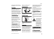
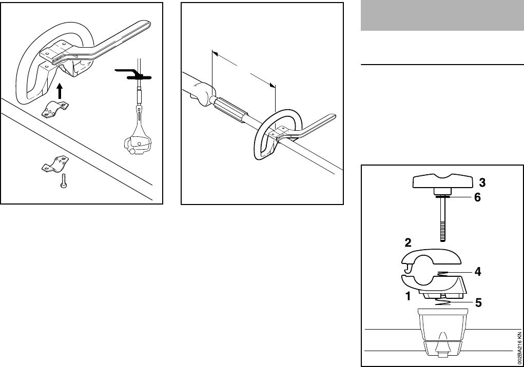
Removing the clamp moldings
N Hold the lower clamp (1) and upper
clamp (2) firmly together.
N Release the wing screw (3) – the
clamps are loose once the wing
screw has been released. They are
pushed apart by the two
springs (4 and 5).
5
4
002BA099 KN
2
3
6
7
A
9
8
4
002BA353 KN
Mounting the Bike Handle