
User Manual
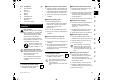
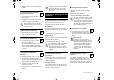
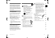
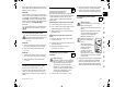
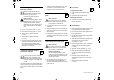
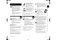
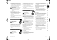
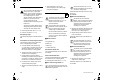
Table Of Contents
- 1. Inhaltsverzeichnis
- 2. Zu dieser Gebrauchsanleitung
- 3. Gerätebeschreibung
- 4. Zu Ihrer Sicherheit
- 5. Symbolbeschreibung
- 6. Lieferumfang
- 7. Gerät betriebsbereit machen
- 8. Hinweise zum Arbeiten
- 8.1 Welches Material kann verarbeitet werden?
- 8.2 Welches Material kann nicht verarbeitet werden?
- 8.3 Maximaler Astdurchmesser
- 8.4 Arbeitsbereich des Bedieners
- 8.5 Arbeitsposition des Gerätes
- 8.6 Richtige Belastung des Geräts
- 8.7 Überlastschutz
- 8.8 Wenn die Schneideinheit des Garten-Häckslers blockiert
- 8.9 Befüllung des Garten- Häckslers
- 9. Sicherheitseinrichtungen
- 10. Gerät in Betrieb nehmen
- 10.1 Garten-Häcksler elektrisch anschließen
- 10.2 Netzleitung anstecken
- 10.3 Netzleitung abstecken
- 10.4 Zugentlastung
- 10.5 Garten-Häcksler einschalten
- 10.6 Garten-Häcksler ausschalten
- 10.7 Drehrichtung der Messerscheiben GHE 450 prüfen
- 10.8 Drehrichtung der Messerscheiben GHE 450 ändern
- 10.9 Astzuführung ausklappen
- 10.10 Astzuführung einklappen
- 10.11 Werkzeugfach
- 10.12 Häckseln
- 11. Wartung
- 11.1 Gerät reinigen
- 11.2 Einfülltrichter ATO 400 demontieren
- 11.3 Messerscheiben demontieren
- 11.4 Messerscheiben montieren
- 11.5 Gegenmesser demontieren
- 11.6 Gegenmesser montieren
- 11.7 Messer wenden
- 11.8 Messer schärfen
- 11.9 Verschleißgrenzen der Messer
- 11.10 Elektromotor und Räder
- 11.11 Serviceintervalle
- 11.12 Aufbewahrung und Winterpause
- 12. Transport
- 13. Verschleiß minimieren und Schäden vermeiden
- 14. Übliche Ersatzteile
- 15. Umweltschutz
- 16. EU- Konformitätserklärung
- 17. Technische Daten
- 18. Fehlersuche
- 19. Serviceplan
- 1. Table of contents
- 2. Notes on the instruction manual
- 3. Machine overview
- 4. For your safety
- 5. Description of symbols
- 6. Standard equipment
- 7. Preparing the machine for operation
- 8. Notes on working with the machine
- 8.1 What material can be processed?
- 8.2 What material cannot be processed?
- 8.3 Maximum branch diameter
- 8.4 Working area for operator
- 8.5 Working position of the machine
- 8.6 Correct machine load
- 8.7 Overload protection
- 8.8 If the cutting unit of the garden shredder becomes blocked
- 8.9 Feeding the garden shredder
- 9. Safety devices
- 10. Operating the machine
- 10.1 Electrical connection of garden shredders
- 10.2 Connecting the power cable
- 10.3 Disconnecting the power cable
- 10.4 Strain relief
- 10.5 Switching on the garden shredder
- 10.6 Switching off the garden shredder
- 10.7 Checking rotational direction of blade discs GHE 450.
- 10.8 Change rotational direction of blade disc GHE 450
- 10.9 Folding out the branch guide
- 10.10 Folding in the branch guide
- 10.11 Tool box
- 10.12 Shredding
- 11. Maintenance
- 11.1 Cleaning the machine
- 11.2 Removing the feed chute ATO 400
- 11.3 Removing the blade discs
- 11.4 Installing the blade discs
- 11.5 Removing the counter-blade
- 11.6 Installing the counter-blade
- 11.7 Reversing the blades
- 11.8 Sharpening the blades
- 11.9 Wear limits of the blades
- 11.10 Electric motor and wheels
- 11.11 Service intervals
- 11.12 Storage and winter break
- 12. Transport
- 13. Minimising wear and preventing damage
- 14. Standard spare parts
- 15. Environmental protection
- 16. EU - Declaration of conformity
- 17. Technical specifications
- 18. Troubleshooting
- 19. Service schedule
- 1. Sommaire
- 2. À propos de ce manuel d’utilisation
- 3. Description de l’appareil
- 4. Consignes de sécurité
- 5. Signification des pictogrammes
- 6. Contenu de l’emballage
- 7. Préparation de l’appareil
- 8. Conseils d’utilisation
- 9. Dispositifs de sécurité
- 10. Mise en service de l’appareil
- 10.1 Branchement du broyeur
- 10.2 Branchement du cordon d’alimentation secteur
- 10.3 Débranchement du cordon d'alimentation secteur
- 10.4 Dispositif de maintien du câble
- 10.5 Mise en marche du broyeur
- 10.6 Arrêt du broyeur
- 10.7 Contrôle du sens de rotation des disques porte-couteaux GHE 450
- 10.8 Modification du sens de rotation des disques porte- couteaux GHE 450
- 10.9 Ouverture du dispositif d’introduction des branches
- 10.10 Fermeture du dispositif d’introduction des branches
- 10.11 Logement des outils de maintenance
- 10.12 Broyage
- 11. Entretien
- 11.1 Nettoyage de l’appareil
- 11.2 Démontage de l’entonnoir de remplissage ATO 400
- 11.3 Démontage des disques porte-couteaux
- 11.4 Montage des disques porte- couteaux
- 11.5 Démontage du contre- couteau
- 11.6 Montage du contre-couteau
- 11.7 Retournement des couteaux
- 11.8 Affûtage des couteaux
- 11.9 Limites d’usure des couteaux
- 11.10 Moteur électrique et roues
- 11.11 Intervalles d’entretien
- 11.12 Rangement de l’appareil et hivernage
- 12. Transport
- 13. Comment limiter l’usure et éviter les dommages
- 14. Pièces de rechange courantes
- 15. Protection de l’environnement
- 16. Déclaration de conformité UE
- 17. Caractéristiques techniques
- 18. Recherche des pannes
- 19. Feuille d’entretien
- 1. Inhoudsopgave
- 2. Over deze gebruiksaanwijzing
- 3. Beschrijving van het apparaat
- 4. Voor uw veiligheid
- 5. Toelichting van de symbolen
- 6. Leveringsomvang
- 7. Apparaat klaarmaken voor gebruik
- 8. Aanwijzingen voor werken
- 8.1 Welk materiaal kan worden verwerkt?
- 8.2 Welk materiaal kan niet worden verwerkt?
- 8.3 Maximale diameter van de takken
- 8.4 Werkgebied van de gebruiker
- 8.5 Werkstand van de machine
- 8.6 Juiste belasting van het apparaat
- 8.7 Overbelastingsbeveiliging
- 8.8 Wat moet ik doen als de snijeenheid van de tuinhakselaar blokkeert?
- 8.9 Vullen van de tuinhakselaar
- 9. Veiligheidsvoorzieningen
- 10. Apparaat in gebruik nemen
- 10.1 Tuinhakselaar aansluiten
- 10.2 Voedingskabel aansluiten
- 10.3 Voedingskabel loskoppelen
- 10.4 Trekontlasting
- 10.5 Tuinhakselaar inschakelen
- 10.6 Tuinhakselaar uitschakelen
- 10.7 Draairichting van messenschijven GHE 450 controleren
- 10.8 Draairichting van de messenschijven GHE 450 wijzigen
- 10.9 Toevoer van takken uitklappen
- 10.10 Toevoer van takken inklappen
- 10.11 Gereedschapsvak
- 10.12 Hakselen
- 11. Onderhoud
- 11.1 Machine reinigen
- 11.2 Vultrechter ATO 400 demonteren
- 11.3 Messenschijven demonteren
- 11.4 Messenschijven monteren
- 11.5 Tegenmes demonteren
- 11.6 Tegenmes monteren
- 11.7 Messen draaien
- 11.8 Messen slijpen
- 11.9 Slijtagegrenzen van de messen
- 11.10 Elektromotor en wielen
- 11.11 Service-intervallen
- 11.12 Opslag en winterpauze
- 12. Transport
- 13. Slijtage minimaliseren en schade voorkomen
- 14. Standaard reserveonderdelen
- 15. Milieubescherming
- 16. EU- conformiteitsverklaring
- 17. Technische gegevens
- 18. Defectopsporing
- 19. Onderhoudsschema
- 1. Indice
- 2. Avvertenze sulle istruzioni per l’uso
- 3. Descrizione dell’apparecchio
- 4. Per la vostra sicurezza
- 5. Descrizione dei simboli
- 6. Equipaggiamento fornito
- 7. Preparazione per la messa in servizio dell'apparecchio
- 8. Istruzioni di lavoro
- 8.1 Quale materiale è possibile trattare?
- 8.2 Quale materiale non è possibile trattare?
- 8.3 Diametro ramo massimo
- 8.4 Zona di lavoro dell'utente
- 8.5 Posizione di lavoro dell‘apparecchio
- 8.6 Sollecitazione corretta dell'apparecchio
- 8.7 Protezione contro sovraccarichi
- 8.8 Eventuale bloccaggio dell'unità di taglio del biotrituratore da giardino
- 8.9 Caricamento del biotrituratore da giardino
- 9. Dispositivi per la sicurezza
- 10. Messa in servizio dell'apparecchio
- 10.1 Collegamento del biotrituratore da giardino alla rete elettrica
- 10.2 Inserimento del cavo di alimentazione
- 10.3 Disinserimento del cavo di alimentazione
- 10.4 Protezione antitrazione cavo
- 10.5 Accensione del biotrituratore da giardino
- 10.6 Spegnimento del biotrituratore da giardino
- 10.7 Controllo del senso di rotazione dei dischi portalame GHE 450
- 10.8 Modifica del senso di rotazione dei dischi portalame GHE 450,
- 10.9 Apertura dell'apertura inserimento rami
- 10.10 Chiusura dell'apertura inserimento rami
- 10.11 Scomparto attrezzi
- 10.12 Trituratura
- 11. Manutenzione
- 11.1 Pulizia dell'apparecchio
- 11.2 Smontaggio dell'imbuto di caricamento ATO 400
- 11.3 Smontaggio dei dischi portalame
- 11.4 Montaggio dei dischi portalame
- 11.5 Smontaggio della controlama
- 11.6 Montaggio della controlama
- 11.7 Inversione delle lame
- 11.8 Affilatura delle lame
- 11.9 Limiti di usura delle lame
- 11.10 Motore elettrico e ruote
- 11.11 Intervalli di manutenzione
- 11.12 Rimessaggio e pausa invernale
- 12. Trasporto
- 13. Minimizzare l’usura ed evitare danni
- 14. Ricambi standard
- 15. Tutela dell’ambiente
- 16. Dichiarazione di conformità EU
- 17. Dati tecnici
- 18. Risoluzione guasti
- 19. Programma Assistenza Tecnica
- 1. Índice
- 2. Acerca de este manual de instrucciones
- 3. Descripción del equipo
- 4. Para su seguridad
- 5. Descripción de los símbolos
- 6. Contenido del suministro
- 7. Preparar el equipo para el servicio
- 8. Indicaciones para el trabajo
- 8.1 ¿Qué materiales se pueden triturar?
- 8.2 ¿Qué materiales no se pueden triturar?
- 8.3 Diámetro máximo de las ramas
- 8.4 Zona de trabajo del usuario
- 8.5 Posición de trabajo del equipo
- 8.6 Carga correcta del equipo
- 8.7 Protección contra sobrecarga
- 8.8 Si se bloquea la unidad de corte de la biotrituradora
- 8.9 Llenado de la biotrituradora
- 9. Dispositivos de seguridad
- 10. Poner el equipo en servicio
- 10.1 Conexión eléctrica de la biotrituradora
- 10.2 Conectar el cable de alimentación
- 10.3 Desconectar el cable de red
- 10.4 Dispositivo antitirones del cable
- 10.5 Conectar la biotrituradora
- 10.6 Desconectar la biotrituradora
- 10.7 Comprobar el sentido de giro de los discos de cuchillas GHE 450
- 10.8 Modificar el sentido de giro de los discos de cuchillas GHE 450
- 10.9 Desplegar la guía de ramas
- 10.10 Replegar la guía de ramas
- 10.11 Compartimento para herramientas
- 10.12 Triturar
- 11. Mantenimiento
- 11.1 Limpiar el equipo
- 11.2 Desmontar la tolva de llenado ATO 400
- 11.3 Desmontar los discos de cuchillas
- 11.4 Montar los discos de cuchillas
- 11.5 Desmontar la contracuchilla
- 11.6 Montar la contracuchilla
- 11.7 Dar la vuelta a las cuchillas
- 11.8 Afilar las cuchillas
- 11.9 Límites de desgaste de las cuchillas
- 11.10 Motor eléctrico y ruedas
- 11.11 Intervalos de servicio
- 11.12 Almacenamiento y parada invernal
- 12. Transporte
- 13. Reducir el desgaste y prevenir daños
- 14. Piezas de recambio habituales
- 15. Protección del medio ambiente
- 16. Declaración de conformidad de la UE
- 17. Datos técnicos
- 18. Localización de anomalías
- 19. Plan de mantenimiento
- 1. Índice
- 2. Sobre este manual de utilização
- 3. Descrição do aparelho
- 4. Para sua segurança
- 5. Descrição de símbolos
- 6. Fornecimento
- 7. Preparar o aparelho para o funcionamento
- 8. Instruções para trabalhar
- 8.1 Que material pode ser processado?
- 8.2 Que material não pode ser processado?
- 8.3 Diâmetro máximo dos ramos
- 8.4 Área de trabalho do utilizador
- 8.5 Posição de trabalho do aparelho
- 8.6 Carga correta do aparelho
- 8.7 Proteção contra sobrecarga
- 8.8 Se a unidade de corte do triturador de jardinagem bloquear
- 8.9 Enchimento do triturador de jardinagem
- 9. Dispositivos de segurança
- 10. Colocar o aparelho em funcionamento
- 10.1 Ligar o triturador de jardinagem à corrente elétrica
- 10.2 Encaixar o cabo de rede
- 10.3 Desencaixar o cabo de rede
- 10.4 Alívio de tracção
- 10.5 Ligar o triturador de jardinagem
- 10.6 Desligar o triturador de jardinagem
- 10.7 Verificar o sentido de rotação dos discos das lâminas GHE 450
- 10.8 Alterar o sentido de rotação dos discos das lâminas GHE 450
- 10.9 Abrir a alimentação de ramos
- 10.10 Rebater a alimentação de ramos
- 10.11 Estojo de ferramentas
- 10.12 Triturar
- 11. Manutenção
- 11.1 Limpar o aparelho
- 11.2 Desmontar o funil de enchimento ATO 400
- 11.3 Desmontar os discos das lâminas
- 11.4 Montar os discos das lâminas
- 11.5 Desmontar a contra-lâmina
- 11.6 Montar a contra-lâmina
- 11.7 Virar as lâminas
- 11.8 Afiar as lâminas
- 11.9 Limites de desgaste das lâminas
- 11.10 Motor elétrico e rodas
- 11.11 Intervalos de manutenção
- 11.12 Arrumação e período de Inverno
- 12. Transporte
- 13. Minimização do desgaste e prevenção de danos
- 14. Peças de reposição comuns
- 15. Proteção do meio ambiente
- 16. Declaração de conformidade UE
- 17. Dados técnicos
- 18. Localização de falhas
- 19. Plano de manutenção
- 1. Innholdsfortegnelse
- 2. Om denne bruksanvisningen
- 3. Maskinbeskrivelse
- 4. For din egen sikkerhet
- 5. Symbolforklaring
- 6. Produktkomponenter
- 7. Gjøre maskinen klar for bruk
- 8. Informasjon om arbeid
- 9. Sikkerhetsutstyr
- 10. Ta maskinen i bruk
- 10.1 Koble kompostkvernen til strømuttaket
- 10.2 Koble til strømledningen
- 10.3 Koble fra strømledningen
- 10.4 Strekkavlastning
- 10.5 Slå på kompostkvernen
- 10.6 Slå av kompostkvernen
- 10.7 Kontrollere dreieretningen til knivskivene GHE 450
- 10.8 Endre dreieretningen til knivskiven GHE 450
- 10.9 Felle ut kvistmatingen
- 10.10 Felle inn kvistmatingen
- 10.11 Verktøyrom
- 10.12 Kverning
- 11. Vedlikehold
- 12. Transport
- 13. Minimere slitasjen og unngå skader
- 14. Vanlige reservedeler
- 15. Miljøvern
- 16. EU-samsvarserklæring
- 17. Tekniske data
- 18. Feilsøking
- 19. Serviceplan
- 1. Innehållsförteckning
- 2. Information om denna bruksanvisning
- 3. Maskinbeskrivning
- 4. För din säkerhet
- 5. Symbolbeskrivning
- 6. Leveransens omfattning
- 7. Göra maskinen klar för användning
- 8. Arbetsanvisningar
- 9. Säkerhetsanordningar
- 10. Ta maskinen i bruk
- 10.1 Ansluta kompostkvarnen till elnätet
- 10.2 Sätta i elkabeln
- 10.3 Koppla bort elkabeln
- 10.4 Dragavlastning
- 10.5 Starta kompostkvarnen
- 10.6 Stänga av kompostkvarnen
- 10.7 Kontrollera rotationsriktning på knivplattorna GHE 450
- 10.8 Ändra knivplattornas rotationsriktning GHE 450
- 10.9 Fälla ut greninmatning
- 10.10 Fälla in greninmatning
- 10.11 Verktygsfack
- 10.12 Hackning
- 11. Underhåll
- 11.1 Göra rent maskinen
- 11.2 Demontera inmatningstratt ATO 400
- 11.3 Demontera knivplattor
- 11.4 Montera knivplattor
- 11.5 Demontera mothållarkniv
- 11.6 Montera mothållarkniv
- 11.7 Vända knivar
- 11.8 Slipa knivar
- 11.9 Slitagegräns knivar
- 11.10 Elmotor och hjul
- 11.11 Serviceintervall
- 11.12 Förvaring och vinteruppehåll
- 12. Transport
- 13. Minimera slitage och förhindra skador
- 14. Vanliga reservdelar
- 15. Miljöskydd
- 16. EU- konformitetsdeklaration
- 17. Tekniska data
- 18. Felsökning
- 19. Serviceschema
- 1. Sisällysluettelo
- 2. Tätä käyttöopasta koskevia tietoja
- 3. Laitekuvaus
- 4. Turvallisuutesi vuoksi
- 5. Kuvasymbolien selitykset
- 6. Toimitussisältö
- 7. Laitteen valmistelu käyttöä varten
- 8. Työskentelyohjeita
- 9. Turvalaitteet
- 10. Laitteen käyttöönotto
- 10.1 Puutarhasilppurin sähköinen liittäminen
- 10.2 Virtajohdon kytkentä
- 10.3 Verkkojohdon irrotus
- 10.4 Vedonestin
- 10.5 Puutarhasilppurin päällekytkentä
- 10.6 Puutarhasilppurin sammutus
- 10.7 Terälautasten pyörimissuunnan GHE 450tarkistaminen
- 10.8 Terälautasten pyörimissuunnan GHE 450 muuttaminen
- 10.9 Oksien syöttötorven avaaminen
- 10.10 Oksien syöttötorven sulkeminen
- 10.11 Työkalukotelo
- 10.12 Silppuaminen
- 11. Huolto
- 11.1 Laitteen puhdistus
- 11.2 Syöttötorven ATO 400 irrotus
- 11.3 Terälautasten irrotus
- 11.4 Terälautasten kiinnitys
- 11.5 Vastaterän irrotus
- 11.6 Vastaterän kiinnitys
- 11.7 Terän kääntäminen
- 11.8 Terien teroitus
- 11.9 Terien kulumisrajat
- 11.10 Sähkömoottori ja pyörät
- 11.11 Huoltovälit
- 11.12 Varastointi ja talvisäilytys
- 12. Kuljetus
- 13. Kulumisen minimointi ja vaurioiden ehkäisy
- 14. Varaosat
- 15. Ympäristönsuojelu
- 16. EU- vaatimustenmukaisuusvaku utus
- 17. Tekniset tiedot
- 18. Vianetsintä
- 19. Huolto-ohjelma
- 1. Indholdsfortegnelse
- 2. Om denne betjeningsvejledning
- 3. Beskrivelse af maskinen
- 4. Sikkerhed
- 5. Symbolforklaring
- 6. Medfølgende dele
- 7. Klargøring af maskinen
- 8. Arbejdsanvisninger
- 8.1 Hvilket materiale kan bearbejdes?
- 8.2 Hvilket materiale kan ikke bearbejdes?
- 8.3 Maksimal grendiameter
- 8.4 Brugerens arbejdsområde
- 8.5 Maskinens arbejdsposition
- 8.6 Korrekt belastning af maskinen
- 8.7 Overbelastningsbeskyttelse
- 8.8 Hvis kompostkværnens skæremodul er blokeret
- 8.9 Påfyldning af kompostkværnen
- 9. Sikkerhedsanordninger
- 10. Tag maskinen i brug
- 10.1 Elektrisk tilslutning af kompostkværn
- 10.2 Sæt netledningen i
- 10.3 Træk stikket ud
- 10.4 Trækaflastning
- 10.5 Tænd for kompostkværnen
- 10.6 Sluk for kompostkværnen
- 10.7 Kontrollér knivskivernes omdrejningsretning GHE 450
- 10.8 Ændring af knivskivernes GHE 450 omdrejningsretning
- 10.9 Udklapning af grentilførsel
- 10.10 Indklapning af grentilførsel
- 10.11 Værktøjsrum
- 10.12 Granulering
- 11. Vedligeholdelse
- 12. Transport
- 13. Sådan minimerer du slid og undgår skader
- 14. Standardreservedele
- 15. Miljøbeskyttelse
- 16. EC- overensstemmelseserklærin g
- 17. Tekniske data
- 18. Fejlsøgning
- 19. Serviceplan
- 1. Spis treści
- 2. Uwagi dotyczące instrukcji obsługi
- 3. Opis urządzenia
- 4. Zasady bezpiecznej pracy
- 4.1 Informacje ogólne
- 4.2 Ostrzeżenie – zagrożenia spowodowane prądem elektrycznym
- 4.3 Odzież robocza i sprzęt ochronny
- 4.4 Transport urządzenia
- 4.5 Przed rozpoczęciem pracy
- 4.6 Praca z urządzeniem
- 4.7 Konserwacja i naprawy
- 4.8 Przechowywanie urządzenia podczas dłuższych przerw w eksploatacji
- 4.9 Utylizacja
- 5. Objaśnienie symboli
- 6. Wyposażenie standardowe
- 7. Przygotowanie urządzenia do pracy
- 8. Wskazówki dotyczące wykonywania pracy
- 8.1 Jakie materiały można rozdrabniać?
- 8.2 Jakich materiałów nie można rozdrabniać?
- 8.3 Maksymalna średnica gałęzi
- 8.4 Obszar pracy użytkownika
- 8.5 Położenie robocze urządzenia
- 8.6 Właściwe obciążenie urządzenia
- 8.7 Zabezpieczenie przed przeciążeniem
- 8.8 Postępowanie po zablokowaniu się zespołu tnącego
- 8.9 Napełnianie rozdrabniacza ogrodowego
- 9. Urządzenia zabezpieczające
- 10. Uruchamianie urządzenia
- 10.1 Podłączanie rozdrabniaczy ogrodowych do zasilania
- 10.2 Podłączanie przewodu elektrycznego
- 10.3 Odłączanie przewodu sieciowego
- 10.4 Zaczep przewodu
- 10.5 Włączanie rozdrabniacza ogrodowego
- 10.6 Wyłączanie rozdrabniacza ogrodowego
- 10.7 Sprawdzanie kierunków obrotu tarcz noży GHE 450
- 10.8 Zmiana kierunku obrotu tarcz noży GHE 450
- 10.9 Rozkładanie leja doprowadzającego gałęzie
- 10.10 Składanie leja doprowadzającego gałęzie
- 10.11 Schowek na narzędzia
- 10.12 Rozdrabnianie
- 11. Konserwacja
- 11.1 Czyszczenie urządzenia
- 11.2 Zdemontowanie leja wsadowego ATO 400
- 11.3 Zdemontowanie tarcz noży
- 11.4 Zamontowanie tarcz noży
- 11.5 Zdemontowanie noża przeciwbieżnego
- 11.6 Zamontowanie noża przeciwbieżnego
- 11.7 Odwracanie noży
- 11.8 Ostrzenie noży
- 11.9 Granica zużycia noży
- 11.10 Silnik elektryczny i koła
- 11.11 Okresy międzyobsługowe
- 11.12 Przechowywanie i przerwa zimowa
- 12. Transport
- 13. Ograniczanie zużycia i zapobieganie uszkodzeniom
- 14. Typowe części zamienne
- 15. Ochrona środowiska
- 16. Deklaracja zgodności UE
- 17. Dane techniczne
- 18. Wykrywanie usterek
- 19. Plan czynności serwisowych
- 1. Kazalo
- 2. O navodilih za uporabo
- 3. Opis naprave
- 4. Za vašo varnost
- 5. Opis simbolov
- 6. Obseg dobave
- 7. Priprava naprave na uporabo
- 8. Napotki za delo
- 8.1 Kakšen material je primeren za predelavo?
- 8.2 Kakšen material ni primeren za predelavo?
- 8.3 Največji dovoljeni premer vej
- 8.4 Uporabnikovo delovno območje
- 8.5 Delovni položaj naprave
- 8.6 Pravilna obremenitev naprave
- 8.7 Zaščita proti preobremenitvi
- 8.8 Če je rezalna glava vrtnega drobilnika blokirana
- 8.9 Polnjenje vrtnega drobilnika
- 9. Varnostna oprema
- 10. Začetek uporabe naprave
- 10.1 Električna priključitev vrtnega drobilnika
- 10.2 Priklop na omrežje
- 10.3 Odklop z omrežja
- 10.4 Zaščita proti izvleku kabla
- 10.5 Vklop vrtnega drobilnika
- 10.6 Izklop vrtnega drobilnika
- 10.7 Preverjanje smeri vrtenja rezalne plošče GHE 450
- 10.8 Spreminjanje smeri vrtenja rezalne plošče GHE 450
- 10.9 Odpiranje dovoda vej
- 10.10 Zložite dovod vej
- 10.11 Predal za orodje
- 10.12 Drobljenje
- 11. Vzdrževanje
- 11.1 Čiščenje naprave
- 11.2 Odstranitev polnilnega lijaka ATO 400
- 11.3 Odstranitev rezalnih plošč
- 11.4 Namestitev rezalnih plošč
- 11.5 Odstranitev nasprotnega noža
- 11.6 Namestitev nasprotnega noža
- 11.7 Obračanje noža
- 11.8 Ostrenje noža
- 11.9 Meje obrabe noža
- 11.10 Elektromotor in kolesa
- 11.11 Servisni intervali
- 11.12 Shranjevanje in prezimovanje
- 12. Transport
- 13. Zmanjšanje obrabe in preprečevanje okvar
- 14. Običajni nadomestni deli
- 15. Varovanje okolja
- 16. EU-izjava o skladnosti
- 17. Tehnični podatki
- 18. Iskanje napak
- 19. Načrt servisiranja

49
DEFRNLITESPTNOSVFIDAPLSL EN
0478 201 9916 A - EN
7.1 Installing the ejection chute
● Move the basic unit (A) into the
installation position shown.
1 Install the ejection chute extension
● Attach the ejection chute extension (E),
engage the hooks (1) in the apertures
on the housing (2), turn downwards and
push on the retainers (3) at the side.
● Screw in the screws (O) and tighten to
1 - 2Nm.
2 Install the guiding plate
● Insert the guiding plate (F).
Ensure that the guides on the guiding
plate (4) are correctly located in the
guides of the ejection chute
extension (5).
● Fit screw (P) and tighten with nut (R).
● Screw in the screws (O) and tighten to
1 - 2Nm.
3 Install the ejection chute plate
● Insert the ejection chute plate (G).
● Screw in the screws (O) and tighten to
1 - 2Nm.
● Fit screws (Q) and tighten with nuts (R).
Any slight tensions occurring in the
ejection chute can be compensated by
readjusting the screws.
7.2 Attaching the chassis
● Move the basic unit (1) into the
installation position shown.
1 Install right and left wheel carrier:
● Position the right wheel carrier (C) on
the basic unit (1) as shown.
● Insert the screw (M) through the bore in
the wheel carrier and screw into the
centre bore using installation tool (S),
but do not tighten.
● Repeat this procedure on the left side.
2 Install the foot and plug:
● Push the foot (L) as far as possible onto
the wheel carrier (C) as shown.
The foot (L) engages in the wheel
carrier (C).
● Carefully drive the plug (K) as far as
possible into the wheel carrier (C).
● Repeat this procedure on the left side.
3 Mount the wheel on the axle:
● Push the retaining ring (N) as far as
possible into the groove in the axle (H).
● Push the wheel (I) onto the axle (H).
● Fit the wheel cap (J).
4 Installing the axle and wheel:
● Push the axle with pre-installed
wheel (3) through the bore (2) in the
wheel carrier, through the motor
cover (4) and through the bore (2) in the
second wheel carrier.
● Push the wheel (I) onto the axle (H).
● Push the retaining ring (N) as far as
possible into the groove in the axle (H).
● Fit the wheel cap (J).
P Flat head bolt
M6x16
1
Q Torx screw
M6x16
2
R M6 nut 3
S Installation tool 1
T Hexagon bolt
M14x130
1
x Instruction manual 1
7. Preparing the machine for
operation
Risk of injury:
Carefully read the section entitled
"For your safety" (Ö 4.) and follow
all the safety instructions before
assembling the garden shredder.
Strictly observe all tightening
torques in the section "Preparing
the machine for operation" (Ö 7.) to
avoid damaging the machine.
Be sure to always wear
gloves. The blade cover
must be installed. (Ö 7.5)
Avoid damage to the machine.
When moving the basic unit into the
installation position shown, ensure
that the electric cable is not
damaged (pinched).
Place cardboard underneath the
machine to protect it from being
scratched.
Item Designation Qty.
3
Only install the wheel carriers as
described, with the bent section
facing outwards.
The axle bore (2) must point to the
rear.
4
When installing, ensure that the
retaining ring (N) engages in the
groove in the axle (H) in order to
prevent the wheel from becoming
loose.