
User Manual
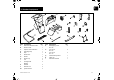
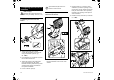
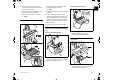
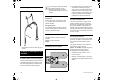

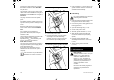


Table Of Contents
- 1. Table of contents
- 2. Notes on the instruction manual
- 3. Machine overview
- 4. For your safety
- 5. Description of symbols
- 6. Standard equipment
- 7. Preparing the machine for operation
- 8. Notes on working with the machine
- 9. Safety devices
- 10. Operating the machine
- 11. Maintenance
- 12. Transport
- 13. Minimising wear and preventing damage
- 14. Standard spare parts
- 15. Environmental protection
- 16. Technical specifications
- 17. Troubleshooting
- 18. Service schedule

EN
13
0478 201 8315 B - EN
● Push the chassis with both wheel
carriers (2) as far as they will go into the
guides on basic unit (A).
● Push wheel carrier (3) into the recess
on the ejection chute extension.
● Fasten the chassis with screws (N)
(1 - 2Nm).
7.3 Installing the discharge flap
● Insert strip (E) into the ejection chute
extension. Install screws (O)
(1 - 2Nm).
● Lift the garden shredder into the upright
position.
● Position discharge flap (D) on the
ejection chute extension. Ensure that
ribs (1) inside the flaps on the left and
right are correctly located in the guide
groove of ejection chute extension (2)
when attaching.
● Press in pins (I) on the left and right.
7.4 Opening and closing the discharge
flap
Opening the discharge flap:
● For shredding, fold discharge flap (D)
upwards and allow tab (1) to engage in
the ejection chute extension.
Closing the discharge flap:
● For transport or space-saving storage,
lift tab (1) slightly and fold away
discharge flap (D) downwards.
7.5 Tool box
● The combination spanner (Q) can be
inserted from below into tool box (2) in
the rear section of chute (1).