
User Manual

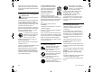
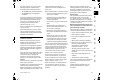
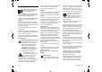
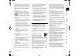
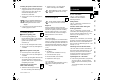
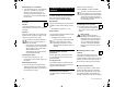
Table Of Contents
- 1. Inhaltsverzeichnis
- 2. Zu dieser Gebrauchsanleitung
- 3. Gerätebeschreibung
- 4. Zu Ihrer Sicherheit
- 5. Symbolbeschreibung
- 6. Lieferumfang
- 7. Gerät betriebsbereit machen
- 8. Bedienelemente
- 9. Hinweise zum Arbeiten
- 10. Sicherheitseinrichtungen
- 11. Gerät in Betrieb nehmen
- 12. Wartung
- 12.1 Gerät reinigen
- 12.2 Einfülltrichter ATO 400 demontieren
- 12.3 Messerscheiben demontieren
- 12.4 Messerscheiben montieren
- 12.5 Gegenmesser demontieren
- 12.6 Gegenmesser montieren
- 12.7 Messer wenden
- 12.8 Messer schärfen
- 12.9 Verschleißgrenzen der Messer
- 12.10 Serviceintervall Verbrennungsmotor
- 12.11 Serviceintervalle
- 12.12 Räder
- 12.13 Aufbewahrung und Winterpause
- 13. Transport
- 14. Verschleiß minimieren und Schäden vermeiden
- 15. Übliche Ersatzteile
- 16. Umweltschutz
- 17. EU- Konformitätserklärung
- 18. Technische Daten
- 19. Fehlersuche
- 20. Serviceplan
- 1. Table of contents
- 2. Notes on the instruction manual
- 3. Machine overview
- 4. For your safety
- 5. Description of symbols
- 6. Standard equipment
- 7. Preparing the machine for operation
- 8. Controls
- 9. Notes on working with the machine
- 10. Safety devices
- 11. Operating the machine
- 12. Maintenance
- 12.1 Cleaning the machine
- 12.2 Removing the feed chute ATO 400
- 12.3 Removing the blade discs
- 12.4 Installing the blade discs
- 12.5 Removing the counter-blade
- 12.6 Installing the counter-blade
- 12.7 Reversing the blades
- 12.8 Sharpening the blades
- 12.9 Wear limits of the blades
- 12.10 Service interval of the combustion engine
- 12.11 Service intervals
- 12.12 Wheels
- 12.13 Storage and winter break
- 13. Transport
- 14. Minimising wear and preventing damage
- 15. Standard spare parts
- 16. Environmental protection
- 17. EU - Declaration of conformity
- 18. Technical specifications
- 19. Troubleshooting
- 20. Service schedule
- 1. Sommaire
- 2. À propos de ce manuel d’utilisation
- 3. Description de l’appareil
- 4. Consignes de sécurité
- 5. Signification des pictogrammes
- 6. Contenu de l’emballage
- 7. Préparation de l’appareil
- 8. Éléments de commande
- 9. Conseils d’utilisation
- 10. Dispositifs de sécurité
- 11. Mise en service de l’appareil
- 12. Entretien
- 12.1 Nettoyage de l’appareil
- 12.2 Démontage de l’entonnoir de remplissage ATO 400
- 12.3 Démontage des disques porte-couteaux
- 12.4 Montage des disques porte- couteaux
- 12.5 Démontage du contre- couteau
- 12.6 Montage du contre-couteau
- 12.7 Retournement des couteaux
- 12.8 Affûtage des couteaux
- 12.9 Limites d’usure des couteaux
- 12.10 Intervalle d’entretien du moteur à combustion
- 12.11 Intervalles d’entretien
- 12.12 Roues
- 12.13 Rangement de l’appareil et hivernage
- 13. Transport
- 14. Comment limiter l’usure et éviter les dommages
- 15. Pièces de rechange courantes
- 16. Protection de l’environnement
- 17. Déclaration de conformité UE
- 18. Caractéristiques techniques
- 19. Recherche des pannes
- 20. Feuille d’entretien
- 1. Inhoudsopgave
- 2. Over deze gebruiksaanwijzing
- 3. Beschrijving van het apparaat
- 4. Voor uw veiligheid
- 5. Toelichting van de symbolen
- 6. Leveringsomvang
- 7. Apparaat klaarmaken voor gebruik
- 8. Bedieningselementen
- 9. Aanwijzingen voor werken
- 10. Veiligheidsvoorzieningen
- 11. Apparaat in gebruik nemen
- 12. Onderhoud
- 12.1 Apparaat reinigen
- 12.2 Vultrechter ATO 400 demonteren
- 12.3 Messenschijven demonteren
- 12.4 Messenschijven monteren
- 12.5 Tegenmes demonteren
- 12.6 Tegenmes monteren
- 12.7 Messen draaien
- 12.8 Messen slijpen
- 12.9 Slijtagegrenzen van de messen
- 12.10 Service-interval verbrandingsmotor
- 12.11 Service-intervallen
- 12.12 Wielen
- 12.13 Opslag en winterpauze
- 13. Transport
- 14. Slijtage minimaliseren en schade voorkomen
- 15. Standaard reserveonderdelen
- 16. Milieubescherming
- 17. EU- conformiteitsverklaring
- 18. Technische gegevens
- 19. Defectopsporing
- 20. Onderhoudsschema
- 1. Indice
- 2. Avvertenze sulle istruzioni per l’uso
- 3. Descrizione dell’apparecchio
- 4. Per la vostra sicurezza
- 5. Descrizione dei simboli
- 6. Equipaggiamento fornito
- 7. Preparazione per la messa in servizio dell'apparecchio
- 7.1 Apertura dell'imballaggio del biotrituratore da giardino
- 7.2 Montaggio del telaio
- 7.3 Smontaggio della copertura lame
- 7.4 Montaggio della copertura lame
- 7.5 Montaggio dell'imbuto di caricamento ATO 400
- 7.6 Montaggio del prolungamento canale di scarico
- 7.7 Montaggio delle lamiere
- 7.8 Carburante e olio motore
- 8. Elementi di comando
- 9. Istruzioni di lavoro
- 10. Dispositivi per la sicurezza
- 11. Messa in servizio dell'apparecchio
- 12. Manutenzione
- 12.1 Pulizia dell'apparecchio
- 12.2 Smontaggio dell'imbuto di caricamento ATO 400
- 12.3 Smontaggio dei dischi portalame
- 12.4 Montaggio dei dischi portalame
- 12.5 Smontaggio della controlama
- 12.6 Montaggio della controlama
- 12.7 Inversione delle lame
- 12.8 Affilatura delle lame
- 12.9 Limiti di usura delle lame
- 12.10 Intervallo di manutenzione del motore a combustione
- 12.11 Intervalli di manutenzione
- 12.12 Ruote
- 12.13 Rimessaggio e pausa invernale
- 13. Trasporto
- 14. Minimizzare l’usura ed evitare danni
- 15. Ricambi standard
- 16. Tutela dell’ambiente
- 17. Dichiarazione di conformità EU
- 18. Dati tecnici
- 19. Risoluzione guasti
- 20. Programma Assistenza Tecnica
- 1. Índice
- 2. Acerca de este manual de instrucciones
- 3. Descripción del equipo
- 4. Para su seguridad
- 5. Descripción de los símbolos
- 6. Contenido del suministro
- 7. Preparar el equipo para el servicio
- 8. Elementos de mando
- 9. Indicaciones para el trabajo
- 10. Dispositivos de seguridad
- 11. Poner el equipo en servicio
- 12. Mantenimiento
- 12.1 Limpiar el equipo
- 12.2 Desmontar la tolva de llenado ATO 400
- 12.3 Desmontar los discos de cuchillas
- 12.4 Montar los discos de cuchillas
- 12.5 Desmontar la contracuchilla
- 12.6 Montar la contracuchilla
- 12.7 Dar la vuelta a las cuchillas
- 12.8 Afilar las cuchillas
- 12.9 Límites de desgaste de las cuchillas
- 12.10 Intervalo de servicio del motor de combustión
- 12.11 Intervalos de servicio
- 12.12 Ruedas
- 12.13 Almacenamiento y parada invernal
- 13. Transporte
- 14. Reducir el desgaste y prevenir daños
- 15. Piezas de recambio habituales
- 16. Protección del medio ambiente
- 17. Declaración de conformidad de la UE
- 18. Datos técnicos
- 19. Localización de anomalías
- 20. Plan de mantenimiento
- 1. Índice
- 2. Sobre este manual de utilização
- 3. Descrição do aparelho
- 4. Para sua segurança
- 5. Descrição de símbolos
- 6. Fornecimento
- 7. Preparar o aparelho para o funcionamento
- 8. Elementos de comando
- 9. Instruções para trabalhar
- 10. Dispositivos de segurança
- 11. Colocar o aparelho em funcionamento
- 12. Manutenção
- 12.1 Limpar o aparelho
- 12.2 Desmontar o funil de enchimento ATO 400
- 12.3 Desmontar os discos das lâminas
- 12.4 Montar os discos das lâminas
- 12.5 Desmontar a contra-lâmina
- 12.6 Montar a contra-lâmina
- 12.7 Virar as lâminas
- 12.8 Afiar as lâminas
- 12.9 Limites de desgaste das lâminas
- 12.10 Intervalo de manutenção do motor de combustão
- 12.11 Intervalos de manutenção
- 12.12 Rodas
- 12.13 Arrumação e período de Inverno
- 13. Transporte
- 14. Minimização do desgaste e prevenção de danos
- 15. Peças de reposição comuns
- 16. Proteção do meio ambiente
- 17. Declaração de conformidade UE
- 18. Dados técnicos
- 19. Localização de falhas
- 20. Plano de manutenção
- 1. Innholdsfortegnelse
- 2. Om denne bruksanvisningen
- 3. Maskinbeskrivelse
- 4. For din egen sikkerhet
- 5. Symbolforklaring
- 6. Produktkomponenter
- 7. Gjøre maskinen klar for bruk
- 8. Betjeningselementer
- 9. Informasjon om arbeid
- 10. Sikkerhetsutstyr
- 11. Ta maskinen i bruk
- 12. Vedlikehold
- 12.1 Rengjøre maskinen
- 12.2 Demontere påfyllingstraktenATO 400
- 12.3 Demontere knivskivene
- 12.4 Montere knivskivene
- 12.5 Demontere motkniven
- 12.6 Montere motkniven
- 12.7 Snu knivene
- 12.8 Slipe knivene
- 12.9 Knivenes slitegrenser
- 12.10 Serviceintervall for forbrenningsmotor
- 12.11 Serviceintervaller
- 12.12 Hjul
- 12.13 Oppbevaring og vinterlagring
- 13. Transport
- 14. Minimere slitasjen og unngå skader
- 15. Vanlige reservedeler
- 16. Miljøvern
- 17. EU-samsvarserklæring
- 18. Tekniske data
- 19. Feilsøking
- 20. Serviceplan
- 1. Innehållsförteckning
- 2. Information om denna bruksanvisning
- 3. Maskinbeskrivning
- 4. För din säkerhet
- 5. Symbolbeskrivning
- 6. Leveransens omfattning
- 7. Göra maskinen klar för användning
- 8. Reglage
- 9. Arbetsanvisningar
- 10. Säkerhetsanordningar
- 11. Ta maskinen i bruk
- 12. Underhåll
- 12.1 Göra rent maskinen
- 12.2 Demontera inmatningstratt ATO 400
- 12.3 Demontera knivplattor
- 12.4 Montera knivplattor
- 12.5 Demontera mothållarkniv
- 12.6 Montera mothållarkniv
- 12.7 Vända knivar
- 12.8 Slipa knivar
- 12.9 Slitagegräns knivar
- 12.10 Serviceintervall förbränningsmotor
- 12.11 Serviceintervall
- 12.12 Hjul
- 12.13 Förvaring och vinteruppehåll
- 13. Transport
- 14. Minimera slitage och förhindra skador
- 15. Vanliga reservdelar
- 16. Miljöskydd
- 17. EU- konformitetsdeklaration
- 18. Tekniska data
- 19. Felsökning
- 20. Serviceschema
- 1. Sisällysluettelo
- 2. Tätä käyttöopasta koskevia tietoja
- 3. Laitekuvaus
- 4. Turvallisuutesi vuoksi
- 5. Kuvasymbolien selitykset
- 6. Toimitussisältö
- 7. Laitteen valmistelu käyttöä varten
- 8. Hallintalaitteet
- 9. Työskentelyohjeita
- 10. Turvalaitteet
- 11. Laitteen käyttöönotto
- 12. Huolto
- 12.1 Laitteen puhdistus
- 12.2 Syöttötorven ATO 400 irrotus
- 12.3 Terälautasten irrotus
- 12.4 Terälautasten kiinnitys
- 12.5 Vastaterän irrotus
- 12.6 Vastaterän kiinnitys
- 12.7 Terän kääntäminen
- 12.8 Terien teroitus
- 12.9 Terien kulumisrajat
- 12.10 Polttomoottorin huoltoväli
- 12.11 Huoltovälit
- 12.12 Pyörät
- 12.13 Varastointi ja talvisäilytys
- 13. Kuljetus
- 14. Kulumisen minimointi ja vaurioiden ehkäisy
- 15. Varaosat
- 16. Ympäristönsuojelu
- 17. EU- vaatimustenmukaisuusvaku utus
- 18. Tekniset tiedot
- 19. Vianetsintä
- 20. Huolto-ohjelma
- 1. Indholdsfortegnelse
- 2. Om denne betjeningsvejledning
- 3. Beskrivelse af maskinen
- 4. Sikkerhed
- 5. Symbolforklaring
- 6. Medfølgende dele
- 7. Klargøring af maskinen
- 8. Betjeningsdele
- 9. Arbejdsanvisninger
- 10. Sikkerhedsanordninger
- 11. Tag maskinen i brug
- 12. Vedligeholdelse
- 12.1 Rengør maskinen
- 12.2 Demonter påfyldningstragten ATO 400
- 12.3 Demontering af knivskiver
- 12.4 Montering af knivskiver
- 12.5 Demonter modkniven
- 12.6 Monter modkniven
- 12.7 Vend kniven
- 12.8 Slib kniven
- 12.9 Slidgrænser for knivene
- 12.10 Serviceinterval forbrændingsmotor
- 12.11 Serviceintervaller
- 12.12 Hjul
- 12.13 Opbevaring og vinterpause
- 13. Transport
- 14. Sådan minimerer du slid og undgår skader
- 15. Standardreservedele
- 16. Miljøbeskyttelse
- 17. EC- overensstemmelseserklærin g
- 18. Tekniske data
- 19. Fejlsøgning
- 20. Serviceplan
- 1. Spis treści
- 2. Uwagi dotyczące instrukcji obsługi
- 3. Opis urządzenia
- 4. Zasady bezpiecznej pracy
- 5. Objaśnienie symboli
- 6. Wyposażenie standardowe
- 7. Przygotowanie urządzenia do pracy
- 8. Elementy obsługi
- 9. Wskazówki dotyczące wykonywania pracy
- 10. Urządzenia zabezpieczające
- 11. Uruchamianie urządzenia
- 12. Konserwacja
- 12.1 Czyszczenie urządzenia
- 12.2 Zdemontowanie leja wsadowego ATO 400
- 12.3 Zdemontowanie tarcz noży
- 12.4 Zamontowanie tarcz noży
- 12.5 Zdemontowanie noża przeciwbieżnego
- 12.6 Zamontowanie noża przeciwbieżnego
- 12.7 Odwracanie noży
- 12.8 Ostrzenie noży
- 12.9 Granica zużycia noży
- 12.10 Okres międzyobsługowy silnika spalinowego
- 12.11 Okresy międzyobsługowe
- 12.12 Koła
- 12.13 Przechowywanie i przerwa zimowa
- 13. Transport
- 14. Ograniczanie zużycia i zapobieganie uszkodzeniom
- 15. Typowe części zamienne
- 16. Ochrona środowiska
- 17. Deklaracja zgodności UE
- 18. Dane techniczne
- 19. Wykrywanie usterek
- 20. Plan czynności serwisowych
- 1. Obsah
- 2. O tomto návode na obsluhu
- 3. Popis stroja
- 4. Pre vašu bezpečnosť
- 5. Popis symbolov
- 6. Rozsah dodávky
- 7. Príprava stroja na prevádzku
- 8. Ovládacie prvky
- 9. Pokyny pre prácu
- 10. Bezpečnostné zariadenia
- 11. Uvedenie stroja do prevádzky
- 12. Údržba
- 12.1 Čistenie stroja
- 12.2 Demontáž podávacieho lievika ATO 400
- 12.3 Demontáž nožových kotúčov
- 12.4 Montáž nožových kotúčov
- 12.5 Demontáž protinoža
- 12.6 Montáž protinoža
- 12.7 Otočenie nožov
- 12.8 Ostrenie nožov
- 12.9 Hranice opotrebovania nožov
- 12.10 Servisný interval spaľovacieho motora
- 12.11 Servisné intervaly
- 12.12 Kolesá
- 12.13 Uskladnenie stroja a zimná prestávka
- 13. Preprava stroja
- 14. Opatrenia na minimalizovanie opotrebovania a na zabránenie vzniku škôd
- 15. Bežné náhradné diely
- 16. Ochrana životného prostredia
- 17. Prehlásenie o zhode výrobcom - EÚ
- 18. Technické údaje
- 19. Hľadanie porúch
- 20. Servisný plán

0478 216 9906 B - EN
56
● Place the cardboard insert (1) on the
ground with the closed side facing
upwards.
● Lift the basic unit (A) with the help of a
second person and place it on the
cardboard insert as shown.
7.2 Attaching the chassis
1 Install right and left wheel carrier:
● Raise the basic unit into the assembly
position. (Ö 7.1)
Attaching the right wheel carrier:
● Position right wheel carrier (B) on the
inside of angled support plate (1). The
bores in the wheel carrier must align
with the bores in the support plate.
● Position a nut (J) on the inside. Insert
screw (I) through the bores (2) in the
support plate and in the wheel carrier
and screw into the nut (J) but do not
tighten.
● Repeat this procedure at the second
bore in the right wheel carrier.
Attaching the left wheel carrier:
● Hold the left wheel carrier (C) with the
bore (1) at the centre bore (2) on the left
side of the basic unit (A).
● Screw in the screw (I) using the
installation tool (T), but do not tighten.
2 Install the foot and plug:
● Push the foot (D) as far as possible
onto right wheel carrier (1) as shown.
The foot engages in the right wheel
carrier.
● Repeat this procedure on the left wheel
carrier.
● Carefully drive plug (E) into right wheel
carrier (2) as far as possible.
● Repeat this procedure on the left wheel
carrier.
3 Mount the wheel on the axle:
● Push the retaining ring (G) as far as
possible into the groove (1) in axle (H).
● Push the wheel (F) onto the axle (H).
4 Install the axle and wheel:
● Push the axle, with pre-installed
wheel (1) through the bores (2) in the
wheel carrier.
● Push the left wheel (F) onto the
axle (1).
● Push the retaining ring (G) as far as
possible into the groove in the axle (3).
● Remove the basic unit from the
cardboard insert.
● Raise the basic unit into the working
position.
7.3 Removing the blade cover
● Hold the blade cover (1) at the
bore and lift off the cover.
7.4 Installing the blade cover
● Insert the blade cover (1) under
the counter-blade (2).
Then press down the blade cover (1).
When properly installed, the blade
cover (1) must lie against the blade disc
correctly.
7.5 Installing the feed chute
ATO 400
● Remove the blade cover. (Ö 7.3)
● Insert the two fastening hooks (1) on
feed chute ATO 400 (K) into the two
openings in the basic unit (2).
● Tilt the feed chute ATO 400 (K)
forwards to the stop.
● Screw in the On / Off switch (3) and
tighten.
7.6 Installing the ejection chute
extension
● Carefully set the machine on its
back.
Risk of injury:
The blade cover must be attached
to prevent any injuries from the
sharp blades. (Ö 7.4)
Attach both wheel carriers to the
basic unit in such a way that the
bores for the axle are located at the
rear (on the tool box side).
4
Risk of injury:
After installing, check that both feet
are seated securely.
Mount the wheels so that the valves
are located on the outside.
In order to prevent the wheel from
becoming loose when installing,
ensure that retaining ring (G)
engages correctly in the groove (1)
in axle (H).
Following assembly, check that the
feed chute ATO 400 is correctly
engaged in both openings in the
basic unit.
Place cardboard underneath in
order to prevent damage.
5
6
7
8