
Instruction Manual
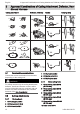
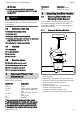
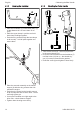
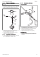
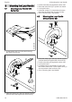
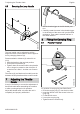
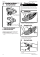
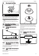

Table Of Contents
- STIHL FS 91, 91 R
- 1 Guide to Using this Manual
- 2 Safety Precautions and Working Techniques
- 2.1 Clothing and equipment
- 2.2 Transporting the machine
- 2.3 Refueling
- 2.4 Before starting
- 2.5 Starting the engine
- 2.6 Holding and guiding the machine
- 2.7 While working
- 2.8 Using mowing heads
- 2.9 When using metal cutting attachments
- 2.10 Vibrations
- 2.11 Maintenance and Repairs
- 2.12 Symbols on Deflectors
- 2.13 Shoulder Strap/Harness
- 2.14 Mowing Head with Nylon Line
- 2.15 STIHL Polycut Mowing Head with Polymer Blades
- 2.16 Risk of Kickout (Blade Thrust) with Metal Cutting Attachments
- 2.17 Grass Cutting Blade
- 2.18 Brush Knife
- 2.19 Circular Saw Blade
- 3 Approved Combinations of Cutting Attachment, Deflector, Handle and Harness
- 4 Approved Power Tool Attachments
- 5 Mounting the Bike Handle
- 6 Mounting the Loop Handle
- 7 Adjusting the Throttle Cable
- 8 Fitting the Carrying Ring
- 9 Mounting the deflector
- 10 Mounting the Cutting Attachment
- 10.1 Placing power tool on the ground
- 10.2 Mounting Hardware for Cutting Attachments
- 10.3 Blocking the Shaft
- 10.4 Removing the Mounting Hardware
- 10.5 Mounting the Cutting Attachment
- 10.6 Fitting Mowing Head with Screw Mounting
- 10.7 Remove the mowing head.
- 10.8 Mounting Metal Cutting Attachments
- 10.9 Removing the Metal Cutting Attachment
- 11 Fuel
- 12 Fueling
- 13 Fitting the Harness
- 14 Balancing the Machine
- 15 Starting / Stopping the Engine
- 16 Transporting the Unit
- 17 Operating Instructions
- 18 Replacing the Air Filter
- 19 Adjusting the Carburetor
- 20 Spark Arresting Screen in Muffler
- 21 Spark Plug
- 22 Engine Running Behavior
- 23 Lubricating the Gearbox
- 24 Storing the Machine
- 25 Sharpening Metal Cutting Blades
- 26 Maintaining the Mowing Head
- 27 Maintenance and Care
- 28 Minimize Wear and Avoid Damage
- 29 Main Parts
- 30 Specifications
- 31 Maintenance and Repairs
- 32 Disposal
- 33 EC Declaration of Conformity

10.3 Blocking the Shaft
6
7
2
002BA330 KN
6
The output shaft (2) must be blocked with the
stop pin (6) or screwdriver (6) to mount or
remove cutting attachments. These parts come
standard with the machine or are available as
special accessories.
► Insert the stop pin (6) or screwdriver (6) in the
hole (7) in the gearbox as far as stop – and
apply slight pressure.
► Rotate shaft, nut or cutting attachment until
the stop pin slips into position and blocks the
shaft.
10.4 Removing the Mounting Hard‐
ware
0000-GXX-1323-A0
4
1
2
3
5
6
► Block the shaft (5) with the stop pin (1).
► Use the combination wrench (2) to loosen and
remove the nut (3) clockwise (left-hand
thread).
► Take the rider plate (4) off the shaft (5). Do not
remove the thrust plate (6).
10.5 Mounting the Cutting Attach‐
ment
WARNING
Risk of injury from thrown objects and contact
with the cutting attachment. Use a deflector that
matches the cutting attachment – see "Mounting
the Deflector".
10.6 Fitting Mowing Head with
Screw Mounting
Keep the instruction leaflet for the mowing head
in a safe place.
1
0000-GXX-1324-A0
2
3
4
► Fit the thrust plate (1).
► Screw the mowing head (3) counterclockwise
on to the shaft (4) as far as stop.
► Block the shaft (4) with the stop pin (2).
► Tighten down the mowing head (3) firmly.
NOTICE
Remove the tool used to block the shaft.
10.7 Remove the mowing head.
► Block the shaft (4) with the stop pin (2).
► Unscrew and remove the mowing head (3)
clockwise.
English 10 Mounting the Cutting Attachment
20 0458-426-8321-B