STIHL FS 55 2 - 33 Instruction Manual
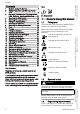
English 3 Your Dr. Nikolas Stihl 1 1.1 Guide to Using this Manual Pictograms The meanings of the pictograms attached to the machine are explained in this manual. Depending on the model concerned, the follow‐ ing pictograms may be attached to your machine.
2 Safety Precautions and Working Techniques English the design, engineering and appearance of our products periodically. If you have a pacemaker: The ignition system of your machine produces an electromagnetic field of very low intensity. This field may interfere with some pacemakers. STIHL recommends that per‐ sons with pacemakers consult their physician and the pacemaker manufacturer to reduce any health risk. Therefore, some changes, modifications and improvements may not be covered in this man‐ ual.
English 2 Safety Precautions and Working Techniques up and confine long hair above your shoulders. Wear safety boots with steel toe caps and non-slip soles. Sturdy shoes with non-slip shoes are permissible only when using mowing heads. WARNING To reduce the risk of eye injuries, wear close-fitting safety glasses in accordance with European Standard EN 166. Make sure the safety glasses are a snug fit. Wear face protection and make sure it is a good fit.
2 Safety Precautions and Working Techniques Do not drop-start the power tool – start the engine as described in the User Manual. The cutting attachment runs on for a short while after releas‐ ing the throttle trigger – coasting effect! Check engine idling: The cutting attachment must remain at a standstill when the engine idles – throttle trigger released. Keep easily combustible materials (e. g., wood chips, bark, dry grass, fuel) away from hot exhaust gases and hot muffler surfaces – risk of fire! 2.
English 2.7 2 Safety Precautions and Working Techniques While working Make sure you always have good balance and secure footing. In the event of impending danger or in an emer‐ gency, switch off the engine immediately - move the slide control/stop switch to STOP or 0. 15m (50ft) Within a wide area around the workplace, there is a risk of accident by ejected objects, therefore ensure that there is no-one within a 15 m radius of the machine.
2 Safety Precautions and Working Techniques Examine the cutting attachment periodically at short intervals and as soon as you note any noticeable changes: – Stop the engine, hold the machine securely, allow the cutting attachment to come to a stop – Check condition and secure fitting; watch out for cracks – Ensure that the cutting blades are sharp – Replace damaged or blunt cutting attachments immediately, even in the event of minor hair‐ line cracks Clean grass and plant residue off the cutting attachment
English 2 Safety Precautions and Working Techniques No general recommendation can be given for the length of usage because it depends on several factors. Use only a spark plug of the type approved by STIHL and make sure it is in good condition – see "Specifications". The period of usage is prolonged by: – Hand protection (wearing warm gloves) – Work breaks Inspect the ignition lead (insulation in good con‐ dition, secure connection).
2 Safety Precautions and Working Techniques Mowing Head with Nylon Line 002BA049 KN 2.14 English If one of the wear limit marks on the PolyCut mowing head is worn through (arrow): Do not continue using the mowing head. Install a new one. There is otherwise a risk of injury from thrown parts of the head. 000BA015 KN It is important to follow the maintenance instruc‐ tions for the PolyCut mowing head. Nylon line achieves a soft cut for edging and trimming around trees, fence posts, etc.
English 2 Safety Precautions and Working Techniques The risk of kickout is greatest when the black area of the rotating cutting attachment comes into contact with a solid object. 2.17 Use for grass and weeds only – sweep the brushcutter in an arc like a scythe. WARNING Grass Cutting Blade Improper use may damage the grass cutting blade – risk of injury from thrown parts. 000BA020 KN Resharpen the grass cutting blade according to instructions when it has dulled noticeably.
3 Approved Combinations of Cutting Attachment, Deflector, Handle and Harness Approved Combinations of Cutting Attachment, Deflector, Han‐ dle and Harness Cutting Attachment 1 Deflector Handle 13 3 2 14 11 4 5 9 14 12 Approved Combinations Select correct combination from the table accord‐ ing to the cutting attachment you intend to use. WARNING For safety reasons only the cutting attachments, deflectors, handles and harnesses shown in each row of the table may be used together.
English 4 4.
5 Mounting the Loop Handle English 5 ► Unscrew the bolt (8) with a combination wrench or hex key wrench – the nut (9) remains in the control handle (10) ► Push the control handle with the throttle trig‐ ger (11) facing toward the gearbox onto the handlebar (4) until the holes (12) align ► Insert and tighten screw (8) 4.3 5.
English 6 Fitting the Carrying Ring ► ► ► ► Position the clamp (6) against the drive tube. Place the barrier bar (2) in position as shown. Line up the holes. Insert the screws (7) in the holes and screw them into the barrier bar (2) as far as stop. ► Go to "Securing the Loop Handle". Securing the Loop Handle Mounting the Loop Handle without Barrier Bar 7 8 A 7 8 4 4 9 002BA615 KN 5.2 5.
7 Mounting the Deflector English 6.2 Polymer Version 1 1 For position of carrying ring see "Main Parts". ► Place the clamp (1) against the drive tube with the tapped hole on the left (viewed from engine). ► Squeeze the two ends of the clamp together and hold in that position. ► Insert the M6x14 screw (2). ► Line up the carrying ring. ► Tighten down the screw firmly. 002BA529 KN 2 002BA142 KN 1 For position of carrying ring see "Main Parts". ► Push the carrying ring (1) over the drive tube.
English 8 Mounting the Cutting Attachment 8 WARNING Deflector (1) is approved for mowing heads only and must therefore be mounted before fitting a mowing head 8.1 Mounting the Cutting Attachment Placing power tool on the ground 002BA263 KN 002BA104 KN 2 WARNING Deflector (2) is approved for grass cutting blades only and must therefore be mounted before fit‐ ting a grass cutting blade. 7.2 ► Shut off the engine.
8 Mounting the Cutting Attachment English Positioning the cutting attachment 3 2 681BA121 KN 1 1 The cutting edges of the grass-cutting blades (1) and (2) may point in either direction – these cut‐ ting attachments must be turned over regularly to reduce one-sided wear.
English 9 Fuel Securing the cutting attachment ► Fit the thrust washer (6) – convex side must face up. ► Fit the rider plate (5) ► Push the offset screwdriver (10) into the hole in the gear as far as it will go; press lightly ► Rotate shaft (8), nut (4) or cutting tool until the offset screwdriver engages and the shaft is blocked ► Use the combination wrench to screw the mounting nut (4) on to the output shaft coun‐ terclockwise and firmly tighten it. WARNING Nuts that move too easily must be replaced.
10 Fueling English Fuel mix ages – only mix sufficient fuel for a few weeks work. Do not store fuel mix for longer than 30 days. Exposure to light, the sun, low or high temperatures can quickly make the fuel mix unusable. The use of the harness is described in the chap‐ ter on "Approved Combinations of Cutting Attachment, Deflector, Handle and Harness". 11.1 Shoulder strap STIHL MotoMix may be stored for up to 2 years without any problems.
English 11.2 12 Balancing the Machine Full Harness ► Attach the carabiner (1) to the carrying ring (2) on the drive tube. 1 3 002BA228 KN 2 ► Put on the harness (1) and close the locking plate (3). ► Adjust the length of the strap – with the machine attached, the carabiner (2) must be about a hand's width below your right hip. ► Balance the machine – see "Balancing the Machine". 12 ► Loosen the screw (3). 12.
13 Starting / Stopping the Engine 12.3 English Detaching the unit from the harness 5 F – normal run position – the engine is running or can start 6 STOP‑0 – engine off – the ignition is switched off 13.1.3 1 1 002BA312 KN 2 2 ► Press down the bar on the carabiner (1) and pull the carrying ring (2) out of the carabiner. 13 Starting / Stopping the Engine 13.1 Version with bike handle 13.1.1 Controls 13.1.
English 13 Starting / Stopping the Engine 13.3 Positions of stop switch All models 6 I – normal run position – the engine can start or is running 7 0 – Stop – engine off – the ignition is switched off 13.2.2 Starting 9 232BA011 KN 8 4 13.3.1 Cranking 233BA014 KN ► Move the stop switch to I. ► Press down the throttle trigger lockout and hold it there. ► Squeeze the throttle trigger until the catch on the tongue (4) can be engaged on the hous‐ ing.
13 Starting / Stopping the Engine English ► Put the unit on the ground: It must rest securely on the engine support and the deflec‐ tor. ► If fitted: Remove the transport guard from the cutting attachment. To reduce the risk of accidents, check that the cutting attachment is not touching the ground of any other obstacles. ► Make sure you have a firm footing, either standing, stooping or kneeling.
English 14 Transporting the Unit ► Set the choke lever to e . ► Set the slide control, trigger lockout lever and throttle trigger to the starting throttle position. ► Start the engine by pulling the starter rope briskly – 10 to 20 pulls may be necessary. 681BA269 KN 13.5.1 If the engine still does not start ► Move the slide control or stop switch to STOP / 0. ► Remove the spark plug – see "Spark Plug". ► Dry the spark plug.
16 Cleaning the Air Filter 15.3 English After Finishing Work Storing for a short period: Wait for the engine to cool down. Empty the fuel tank and keep the machine in a dry place, well away from sources of ignition, until you need it again. For longer outof-service periods – see "Storing the Machine". 16 16.1 Cleaning the Air Filter If there is a noticeable loss of engine power 4 232BA018 KN 3 2 232BA017 KN 1 ► Set the choke lever to g.
English 17.1 18 Spark Plug Adjusting Idle Speed 232BA081 KN 1 L ► Pull off the spark plug boot (1). ► Unscrew the spark plug. A ► Start and warm up the engine. 17.1.1 Engine stops while idling ► Turn the idle speed screw (LA) slowly clock‐ wise until the engine runs smoothly – the cut‐ ting attachment must not rotate. 17.1.
19 Engine Running Behavior Arcing may occur if the adapter nut (1) is loose or missing. Working in an easily combustible or explosive atmosphere may cause a fire or an explosion. This can result result in serious inju‐ ries or damage to property. 1 2 ► Use resistor type spark plugs with a properly tightened adapter nut. Installing the spark plug ► Screw home the spark plug, fit the boot and press it down firmly.
English 23 Inspections and Maintenance by Dealer WARNING If there are signs of serious wear, replace the complete mowing head. The nylon mowing line is referred to as "nylon line" or "line" in the following. The mowing head is supplied with illustrated instructions for replacing the nylon line. Keep the instructions for the mowing head in a safe place. ► If necessary, remove the mowing head. 22.
24 Maintenance and Care Visual inspection (condi‐ X X tion, leaks) Clean X Control handle Check operation X X Air filter Clean X Replace X Manual fuel pump (if fit‐ Check X ted) Have repaired by servic‐ X ing dealer1) Pickup body (filter) in fuel Check X tank Have replaced by serv‐ X X icing dealer1) Fuel tank Clean X Carburetor Check idle adjustment – X X the cutting attachment must not rotate Readjust idle speed Spark plug Readjust electrode gap X Replace after every 100 operating hours Cooling air inlet
English Minimize Wear and Avoid Damage Observing the instructions in this manual helps reduce the risk of unnecessary wear and dam‐ age to the power tool. The power tool must be operated, maintained and stored with the due care and attention described in this owner's manual. The user is responsible for all damage caused by non-observance of the safety precautions, oper‐ ating and maintenance instructions in this man‐ ual.
English 27 Specifications 16 Tank 27.2 17 Machine Support Electronic magneto ignition 18 Loop Handle Spark plug (resistor type): NGK CMR6H Electrode gap: 0.5 mm 19 Barrier Bar (country specific) Ignition System 20 Shaft 27.3 21 Stop Switch All position diaphragm carburetor with integral fuel pump # Serial Number Fuel System Fuel tank capacity: 27.4 330 cc (0.33 l) Weight Dry, without cutting attachment and deflector FS 55: 4.9 kg FS 55 R: 4.4 kg 27.
English 27.6 28 Maintenance and Repairs REACH REACH is an EC regulation and stands for the Registration, Evaluation, Authorisation and Restriction of Chemical substances. 27.7 Exhaust Emissions The CO2value measured in the EU type approval procedure is specified at www.stihl.com/co2.
30 EC Declaration of Conformity English Technical documents deposited at: ANDREAS STIHL AG & Co. KG Produktzulassung The year of manufacture and serial number are applied to the product. Done at Waiblingen, 03.02.2020 ANDREAS STIHL AG & Co. KG pp Dr.
English 34 30 EC Declaration of Conformity 0458-233-0121-H
30 EC Declaration of Conformity 0458-233-0121-H English 35
0458-233-0121-H *04582330121H* www.stihl.