
Owner's Manual


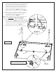
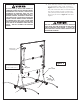
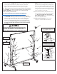

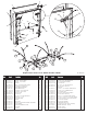

Table Of Contents

Figure 3
Note: Slide U-Support back and forth
until you see the hole if necessary.
Table Top
Assembly
4. Rotate U-support (#21) that is on bottom of Table Top
Assembly until you see the screw holes in the slots of U-
clips (#22). Slide U-support (#21) side to side if
necessary to see holes. See Figure 3.
5. Insert Screw (#35) through slot in U-clip (#22) and into
U-support (#21). See Figure 3. Thread screw all the way
into U-support until it touches the back of the tube. There
should be about 3/8” of screw (#35) left sticking out.
Repeat for other screw as shown in Figure 3.
6. Repeat steps 3 through 5 on other table top assembly.
4
Detail 1
24
38
34
23
44
19
19
25
26
3.
flat surface. Use the shipping carton to protect the painted
surface of the table top. Attach legs (#19) to table top
with Hex Bolt (#24), two Plastic Washers (#38) and
Locknut (#34). Attach leg brace to Leg Mounting Bracket
(#25) with Phillips Head Screw (#23) and #10-24
Locknut (#44) as shown in Detail 1. Attach leg caps
(#26) to bottom of the legs (#19) as shown in Figure 3.
Lay Table Top Assembly painted side down, on a smooth,
21
35
35
Leg Brace
Note: To aid in assembly you can use a cordless drill and
Phillips bit for Step 5 only. Wear safety glasses.
21
22
35