
Owner's Manual


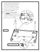
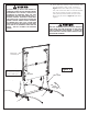

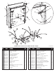

Table Of Contents

3
1. Attach Wood Bottom Board (#15) to Caster Beam
Assemblies (#7) as shown in Figure 1. Turn
Caster Beams as shown and attach board with four
Carriage Bolts (#31) and four Wing Nuts (#32).
Tighten Thumb Screws securely.
Figure 1
READ AND FOLLOW ALL ASSEMBLY, OPERATING, AND
SAFETY INSTRUCTIONS CAREFULLY. AT LEAST TWO (2)
ADULTS ARE NEEDED TO PUT THIS TABLE TOGETHER!
2. Attach Strut Tubes (#17) and Linkages (#16) to Caster Beam Assemblies (#7) as shown in Figure 2.
a) Loosen Bolts (#13) and Nuts (#28) so that Strut Tube (#17) can fit between Support Plate (#43) and Caster
Beam (#7) as shown in the Top View and Figure 2.
b) Slide one Hex Bolt (#27) through Caster Beam (#7), one Plastic Washer (#39), Strut Tube (#17), Plastic Washer
(#39), Support Plate (#43) Spacer (#36), Linkage (#16) and Locknut (#28) as shown in Figure 2 Top View.
c) Repeat on other end of Caster Beam (#7) and on second Caster Beam.
d) Tighten Bolts (#13) and Nuts (#28) securely.
e) Tighten Nuts (#28) on Bolts (#27) securely.
Note: Support Plate (#43)
must be on inside of Caster
Rail (#7) as shown.
31
32
31
32
7
15
43
7
Figure 2
36
28
16
7
16
17
27
39
Top View
27
39
36
28
17
43
12
16
13
13
7
17
Note: Strut tubes must
be turned as shown or
table will not operate
correctly.