
Owner's Manual
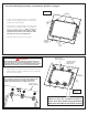
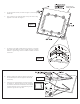
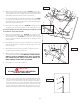
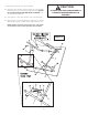
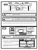
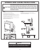
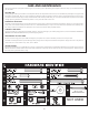
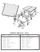
Table Of Contents

2
1. Lay table top #1 painted side down, on a smooth, flat
surface. Use the shipping container to protect the
painted surface of the table top.
2. Assemble the two “L” tubes and the center tubes that
make up the “U” Support and the “U” Leg. Align on
Table Top as shown in Figure 1. Note: “U” Leg is
larger and wider than the U Support. The U-
leg should be installed on the end of the table
half with the end rail mounting holes.
3. Put plastic caps #13 on the end of U-leg #2.
Figure 1
IMPORTANT: U-Leg is wider than U-support.
Make sure they are assembled exactly as
shown. If not, there will be a large gap between
table halves and table will not operate properly!
For aid in identifying hardware, see hardware identifier on page 9.
CAUTION:
4. Align the holes in the Large U-clips #34 and the U-clips #3
with pilot holes in table top assembly and secure with twenty
four screws #20 as shown.
3
3
20
3
3
34
34
34
7
U-support
2
U-Leg
Figure 2
This end is the
middle of the table
All screws shown
are (#20) sheet
metal screws.
U-support
7
End Rail
Mounting
Holes
2
U-Leg
13
Plastic
Cap
13
Plastic
Cap
IMPORTANT:
This end is the
middle of the table
Be sure that slot in the three U-clips #34 and the three
U-clips #3 all face the same direction (toward the
middle of the table with the U-support) as shown.
WHEN ASSEMBLING TABLE, IT IS EXTREMELY IMPORTANT THAT THE U-
CLIPS (#34) AND (#3) BE TURNED AS SHOWN HERE. IF U-CLIPS ARE
TURNED INCORRECTLY, YOU WILL DO IRREPARABLE DAMAGE TO YOUR
TABLE WHEN YOU ATTEMPT TO OPEN IT TO THE PLAYING POSITION.