OWNER’S MANUAL TABLE TENNIS TABLE MODEL NO. T8521 Please Do Not Return This Product to the Store! Contact Escalade® Sports customer service department at: Phone: 1-866-873-3528 Toll-Free! Fax: 1-866-873-3533 Toll-Free! E-mail: customerservice@escaladesports.com Escalade® Sports products may be manufactured and/or licensed under the following patents. 6120397, 5816957, 5769744, 5119741, 4911085, 4717157, D460140, D420563, 8414431 Additional patents may be pending.
PRE- ASSEMBLY TIPS PRE-ASSEMBLY TIPS 1. Read this manual carefully before starting assembly. Read each step completely before beginning each step. 2. Some smaller parts may be shipped inside larger parts. Check inside all parts and cartons before assembling or ordering parts. 3. To make assembly easier, use the Hardware Identifier on page 3 to identify and sort all fasteners. Check all cartons for kits. All hardware may not be located in one kit. 4. Do not tighten hardware until instructed to do so.
NOTE: Sorting your hardware ahead of time will speed up assembly time. Sort all your hardware now so it will be ready before you start assembly. HARDWARE IDENTIFIER 34 27 1/4-20 Locknut (Qty. 20) 3/8-16 x 3 1/2 Hex Head Bolt (Qty. 4) 28 29 3/8-16 Locknut (Qty. 4) 30 1/4-20 X 1 1/2 Phillips Truss Head Screw (Qty. 4) 1/4-20 X 2 3/4 Hex Head Bolt (Qty. 4) 32 31 1/4-20 X 3 1/4 Carriage Bolt (Qty. 4) 35 1/4-20 Wing Nut (Qty. 4) 37 38 3/8" Long Spacer (Qty. 4) 1/4" Plastic Washer (Qty.
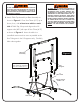
HARDWARE NEEDED On the top of each page you will find a picture of the Hardware Needed (to scale) along with the Quantity, Key# and Description. You can lay the hardware on 31 1/4-20 X 3 1/4 Carriage Bolt (Qty. 4) 32 ASSEMBLY TIP the picture to identify and sort the hardware. 1/4-20 Wing Nut (Qty. 4) CAUTION: 1. Attach Wood Bottom Board (#15) to Caster Beam Assemblies (#8) READ AND FOLLOW ALL ASSEMBLY, OPERATING, AND SAFETY INSTRUCTIONS CAREFULLY.
HARDWARE NEEDED 27 28 3/8-16 x 3 1/2 Hex Head Bolt 36 3/8-16 Locknut (Qty. 4) (Qty. 4) 39 3/4" Long Spacer (Qty. 4) 3/8" Plastic Washer (Qty. 8) 2. Attach Strut Tubes (#17) and White Linkages (#16) to Caster Beam Assemblies (#8) as shown in Figure 2. a) If necessary loosen Bolts (#13) and Nuts (#28) so that Strut Tube (#17) can fit between Support Plate (#43) and Caster Beam (#8) as shown in the Top View and Figure 2.
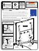
3. Rotate U-support (#21) that is on bottom of Table Top until you see the screw holes in the slots of U-clips (#22). HARDWARE NEEDED If necessary Slide U-support (#21) side to side and back and forth to see holes. See Figure 3 & Detail A. NOTE: To aid in assembly use a cordless drill but DO NOT over tighten screws. Wear safety glasses. 35 4. Insert Screw (#35) through slot in U-clip (#22) and into U-support (#21). See Figure 3 & Detail A.
DO NOT OPEN THE TABLE TO PLAYING POSITION UNTIL BOTH TOPS ARE INSTALLED! DO NOT LEAVE TABLE STANDING UNATTENDED. IT COULD BE KNOCKED OVER CAUSING SERIOUS BODILY INJURY OR PROPERTY DAMAGE. 6. Attach Table Top Assembly to Base Assembly as shown in Figure 4. Pivot Strut Tubes (#17) up as shown; then, with at least one adult on each AT LEAST TWO (2) ADULTS ARE NEEDED TO COMPLETE THE REST OF THIS ASSEMBLY! WHEN ASSEMBLING TOPS TO BASE, HANDLE TOP ASSEMBLIES BY GRASPING ONLY THE TOPS THEMSELVES.
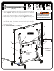
HARDWARE NEEDED 30 34 1/4-20 X 1 1/2 Phillips Truss Head Screw (Qty. 2) 38 1/4" Plastic Washer (Qty. 2) 1/4-20 Locknut (Qty. 2) DO NOT OPEN THE TABLE TO PLAYING POSITION UNTIL BOTH TOPS ARE INSTALLED! DO NOT LEAVE TABLE STANDING UNATTENDED. IT COULD BE KNOCKED OVER CAUSING SERIOUS BODILY INJURY OR PROPERTY DAMAGE. Note: If hinge (#18) is positioned as shown in Detail B, you will have to rotate the hinge to the position shown in Detail C.
HARDWARE NEEDED 29 34 1/4-20 X 2 3/4 Hex Head Bolt (Qty. 2) 37 1/4-20 Locknut (Qty. 2) 5 #8 X 9/16 Screw (Qty. 2) 3/8" Long Spacer (Qty. 2) 8. Secure U-support tube (#21) to Strut Tubes (#17) with two Screws (#5) as shown in Figure 6. Align holes in U-support with holes in Strut Tubes and thread screw (#5) into hole in Strut Tube (#17). Tighten screws all the way but be careful not to over tighten as you could strip threads on screws. 9. Attach Linkages (#16) to Leg (#19) as shown in Figure 6.
OPENING AND CLOSING INSTRUCTIONS CAUTION: EXERCISE CAUTION IN OPENING/CLOSING TABLE. SMALL CHILDREN, OR CHILDREN NOT PROPERLY INSTRUCTED IN ITS USE, MUST NOT BE ALLOWED TO OPEN/CLOSE TABLE. IMPROPER HANDLING AND MISUSE CAN RESULT IN SERIOUS INJURY OR DAMAGE. DO NOT CLIMB, STAND, OR JUMP ON TABLE. MOISTURE AND CONDENSATION WILL DAMAGE PLAYING SURFACE OF THIS TABLE. STORE IN DRY, INDOOR PLACE. TO OPEN: 1. Hold center of top edge. Gently pull outward to midway position. ....
by firmly gripping the vertical net post within height adjustment slot 3. Storage Caution: To prevent damage to the net system and/or table top, the post assembly must be pivoted toward side of table before lifting table tops to storage position. Loosen knob and pivot net post toward table side as far as it will go. Retighten Knob.
Replacement Parts List for Model Number T8521 Key# 1 2 3 4 5 6 7 8 9 10 11 12 13 14 15 16 17 18 19 20 21 22 23 24 25 26 27 28 29 30 31 32 33 34 35 36 37 38 39 40 41 42 43 44 Part # 4A-5532-00 2S-4644-05 2S-4645-05 2S-5137-02 1B-4082-99 3M-6273-00 3M-1027-00 8S-6841-10 2Q-4023-03 2Q-4024-03 2B-4043-02 3M-6884-00 1B-6195-02 3M-6274-00 2W-6258-02 8S-6842-05 8S-6850-07 4A-5542-00 8S-6866-02 2S-4597-01 8S-6851-04 2S-6879-10 2S-4642-01 1B-4137-02 1A-6341-02 3M-6248-00 1B-6495-02 2B-4053-02 1B-4135-02 1B-4097-0
7 33 4 40 3 23 40 1 *PARTS LIST ON PREVIOUS PAGE.
ONE YEAR LIMITED WARRANTY This consumer warranty extends to the original consumer purchase of any ESCALADE® SPORTS Product (hereinafter referred as the "Product"). WARRANTY DURATION: This Product is warranted to the original consumer purchase of a period of one (1) year from the original purchase.
MANUAL DEL USUARIO MESA DE TENNIS DE MESA NÚMERO DE MODELÓ T8521 Por favor no regrese este producto a la tienda! Contacte al departamento de servicio al cliente de Escalade® Sports: Teléfono:1-866-873-3528 ¡Sin costo alguno! Fax:1-866-873-3533 ¡Sin costo alguno! E-mail:tabletennis@escaladesports.com Los productos Escalade® Sports se pueden fabricar y/o producir bajo las siguientes patentes. 6120397, 5816957, 5769744, 5119741, 4911085, 4717157, D460140, D420563, 8414431 Puede haber patentes en trámite.
CONSEJOS ANTES DE INSTALACIÓN CONSEJOS ANTES DE INSTALACIÓN 1. Lea este manual cuidadosamente antes de empezar a ensamblar. Lea completamente cada uno de los pasos antes de empezar a ensamblar cada paso. 2. Algunas partes pequeñas pueden ser empacadas dentro de las partes grandes. Verifique en el interior de todas las partes y cartones antes de ensamblar o solicitar partes. 3.
Separando sus tuercas y tornillos antes de empezar reducirá el tiempo de instalación. Separe las partes ahora para que este listo antes de empezar la instalación. NOTA: IDENTIFICADOR DE TUERCAS Y TORNILLOS 34 27 1/4-20 Tuerca (Cant. 20) 3/8-16 x 3 1/2 Tornillo (Cant. 4) 28 29 3/8-16 Tuerca (Cant. 4) 30 1/4-20 X 2 3/4 Tornillo (Cant. 4) 1/4-20 X 1 1/2 Tornillo Phillips (Cant. 4) 5 32 31 1/4-20 X 3 1/4 Tornillo de Carruaje (Cant. 4) 35 1/4-20 Tuerca de Mariposa (Cant.
NECESITA: 31 1/4-20 X 3 1/4 Tornillo de Carruaje (Cant. 4) CONSEJOS DE INSTALACIÓN 32 En la parte superior de cada página encontrará un dibujo del las tuercas y tornillos necesarios (a escala) junto con la cantidad, número de clave y descripción. Puede colocar las partes sobre el dibujo para identificar y clasificarlas. 1/4-20 Tuerca de Mariposa (Cant. 4) PRECAUCIÓN: 1.
NECESITA: 27 28 3/8-16 x 3 1/2 Tornillo 36 3/8-16 Tuerca (Cant. 4) (Cant. 4) 39 3/4" Separador (Cant. 4) 3/8" Rondana de Plástico (Cant. 8) 2. Una los Tubos Estructurales (#17) y los Tubos Conectores blancos (#16) a los Carriles con Llantas (#8) como están mostrados en la Figura 2.
3. Gire el tubo de soporte "U" (#21) que se encuentra en la base del tablero, hasta que vea los orificios atra vez de las abrazaderas en “U” (#22) donde van los tornillos. Si es necesario deslice el tubo de soporte "U" (#21) de lado a lado y hacia atrás y adelante para ver los orificios. Ver la Figura 3 y el Detalle A. NECESITA: 35 NOTA: Para facilitar la instalación se puede utilizar un taladro inalámbrico pero NO sobre apriete el Tornillo. Use anteojos de seguridad. 4.
ADVERTENCIA: ADVERTENCIA: NO ABRA LA MESA EN LA POSICIÓN DE JUEGO, HASTA QUE AMBAS MITADES DE LA MESA ESTÉN INSTALADAS! NO DEJE LA MESA LEVANTADA SOLA. PODRÍA CAERSE SOBRE ALGUIEN CAUSANDO HERIDAS SERIAS Ó DAÑO DE PROPIEDAD. 6. Una el Tablero Ensamblado a la base, como lo muestra en la Figura 4.
NECESITA: 30 ADVERTENCIA: 34 38 1/4-20 X 1 1/2 Tornillo Phillips (Cant. 2) 1/4" Rondana de Plástico (Cant. 2) 1/4-20 Tuerca (Cant. 2) NO ABRA LA MESA EN LA POSICIÓN DE JUEGO, HASTA QUE AMBAS MITADES DE LA MESA ESTÉN INSTALADAS! NO DEJE LA MESA LEVANTADA SOLA. PODRÍA CAERSE SOBRE ALGUIEN CAUSANDO HERIDAS SERIAS Ó DAÑO DE PROPIEDAD. Nota: Si la bisagra (#18) esta colocada como se muestra en Detalle B, usted tendrá que girar la bisagra a la posición que se muestra en Detalle C.
NECESITA: 29 34 1/4-20 X 2 3/4 Tornillo (Cant. 2) 37 1/4-20 Tuerca (Cant. 2) 5 8. Atornille el Tubo del Soporte-U (#21) a los Tubos Estructurales (#17) con los dos Tornillos (#5) como se muestra en Figura 6. Alinie los orificios de los tubos de Soporte-U con los Tubos Estructurales e inserte los Tornillos (#5) en los orificios de los Tubos Estructurales (#17).
INSTRUCCIONES PARA ABRIR Y CERRAR ADVERTENCIA! PONGA ATENCIÓN AL ABRIR Y AL CERRAR LA MESA. MENORES DE EDAD QUE NO SABEN EL USO APROPIADO DE LAS INSTRUCCIONES NO SE LES DEBE PERMITIR ABRIR Y CERRAR LA MESA. EL MANEJO O USO INCORRECTO DE LA MESA PUEDE CAUSAR LESIONES GRAVES O DAÑOS MATERIALES. NO DEBEN DE PARARSE, SUBIRSE O BRINCAR SOBRE LA MESA. LA HUMEDAD Y LA CONDENSACIÓN DAÑARÍAN LA SUPERFICIE DE LA MESA. LA MESA DEBE ESTAR EN EL INTERIOR Y EN UN LUGAR SECO. PARA ABRIR: 1. 2. 3. 4.
2. Ajustes A - Ajuste la tensión general de la red aflojando levemente la manija y moviendo el soporte. Ajuste suavemente la manija. El soporte deberá estar en escuadra con la mesa cuando haya llegado al tope. (Ver Descripción del sistema de red) DESCRIPCION DEL SISTEMA DE RED B - Ajuste la tensión de la cuerda con la cadena de cuentas a cada lado. Asegúrese de que la cadena esté ajustada en el gancho.
Lista de partes para el modelo T8521 Núm de Ref.
7 33 4 40 3 23 40 1 *LISTA DE PARTES EN LA PAGINA ANTERIOR.
GARANTÍA LIMITADA POR UN AÑO Esta garantía es aplicable para consumidores de la compra original de cualquier producto ESCALADE® SPORTS (en adelante denominado el "Producto"). DURACIÓN DE LA GARANTÍA: Se garantiza este Producto al comprador original por un período de un (1) año a partir de la fecha de compra.