
Owners manual


1
15
64
"
1
11
64
"
1
11
64
"
1
15
64
"
8
10
10
43
8
11
9
10
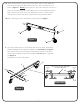
1A. Attach Caster Wheels (#9 & #10) to Caster Beam. Slide a Caster Wheel with
Lock (#10) through Caster Beam (#8) and secure it with a Push Nut (#11) as
shown in Figure 1. Gently tap the Push Nut (#11) with a hammer to secure it in
place. On the other end of the Caster Beam attach a Caster Wheel without Lock
(#9). Make sure you have one Caster Wheel with Lock and a Caster Wheel
without Lock for each Caster Beam. Repeat step for second Caster Beam.
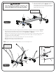
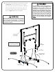
2.
between middle holes to side holes is different, see Front View of Figure 2.
Attach Stop Spools (#12) and Support Plates (#43) to side of Caster Beam
without logo with Bolts (#13) and Nuts (#28) but do not tighten completely.
See Figure 2.
Repeat step for second Caster Beam.
Lay Support Plates (#43) on Caster Beam (#8) to line up holes, the distance
Figure 1
13
28
43
12
8
Longer
Shorter
Figure 2
Front View
3
Longer
Shorter
Match Support Plate (#43)
with Caster Beam (#8).
holes in
14
1B.Attach Tube Plugs (#14) to Caster Beam (#8) as shown in Figure 1.