STIGA Silex 75-G Silex 75R-B Silex 75R-H Silex 75R-HX BRUKSANVISNING SV .... 4 KÄYTTÖOHJEET FI ... 12 BRUGSANVISNING DA x19 BRUKSANVISNING NO .26 GEBRAUCHSANWEISUNG DE...33 INSTRUCTIONS FOR USE EN...41 MODE D’EMPLOI FR....48 GEBRUIKSAANWIJZING NL...56 ISTRUZIONI PER L’USO IT.....64 INSTRUCCIONES DE USO ES ....72 INSTRUÇõES DE UTILIZAÇÃO PT ...80 INSTRUKCJA OBS£UGI PL....88 »HC“P”K÷»fl œOÀ‹«Œ¬¿“EÀfl RU...
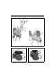
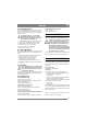
1 A E B C D F G P Q H J K R L M N O S 2 3 75-G B E A N 75R-H O A E P B Q P R J J K R 2 K
4 A 75R-HX 5 E B P T Q J R K 7 6 U T X L Y V Z S 8 T 9 A B 3
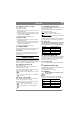
ENGLISH 1 SYMBOLS The following symbols can be found on the rotary cultivator/in these instructions. These will provide a reminder of the care and attention that is required during operation. If any symbol is missing, has been damaged or is illegible, it must immediately be replaced with a new one. This is what the symbols mean: Warning! Read the owner’s manual before operating the machine. Warning! Rotating blade.
GB ENGLISH • Wear tightly fitting clothes and heavy-duty shoes which completely cover the feet. • The tank should only be half full when operating on slopes. Petrol can leak out. • The engine must be stopped in the following circumstances: • When the machine is left unattended • Before the machine is filled up with petrol • Always make sure you have a good footing, especially on slopes. • Check that no one is in front of you or beside you when starting the blades. Keep a steady grip on the steering.
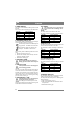
GB ENGLISH 3.5 Cable for reverse control 4.3 Throttle and stop (1:C) Only applies to 75R. The cable is marked R. 1. Pull the cable up under the cover (1:G) and over the handle’s screws. 2. Hook the cable in the reverse control (1:A) and insert the cable in the gap in the cable housing’s mounting on the left handle. 3. Adjust the cable sleeve if necessary. The control determines the engine’s rpm and has start and stop positions. The throttle control determines the speed and is used to stop the engine.
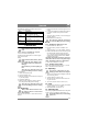
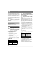
GB ENGLISH 4.10Oil draining The screw is removed when used engine oil is to be drained. The screw is shown according to the table below: Machine 75-G 75R-B 75R-H 75R-HX Figure:Position 2:K 1:K 3:K 4:K 4.11Auxiliary wheel (1:L) The auxiliary wheel is intended to assist transport of the machine and has two positions. The auxiliary wheel must be folded up during operation – Installed in the front hole. The auxiliary wheel must be down for transport – Installed in the rear hole.
GB ENGLISH The different operating properties are shown according to the table below: Holes Left Middle Right Properties The machine works itself forward , angled to the left. The machine works itself forward without being angled to either side. The machine works itself forward, angled to the right. 5 OPERATION 5.1 Fuel Read and understand all safety instructions. No fires or smoking near to petrol. Use 92-95 octane lead free petrol. Oil-mixed petrol designed for 2-stroke engines must never be used.
GB ENGLISH The optimum working depth varies with soil conditions. The working depth is determined by how hard the depth skid is pushed down during propulsion. Operate and test. Drive 2-3 times in different directions for best results. Never operate the machine in wet soil. Clumps of earth are created that are then difficult to break-up. Hard and dry soil requires an extra run, at right angles to the first. WARNING! Never overload a new machine. Drive carefully for the first 5 hours.
GB ENGLISH 7.4 Changing the oil Change the oil the first time after 2 hours of operation, and subsequently every 25 hours of operation or at least once a season. Change oil when the engine is warm. The engine oil may be very hot if it is drained off directly after the engine is shut off. So allow the engine to cool a few minutes before draining the oil. 1. Lean the machine slightly so that the oil draining plug is the lowest point of the engine. 2. Unscrew the oil draining plug. See “4.10”. 3.